In this NetApp training tutorial, I will explain NetApp Broadcast Domains and Failover Groups. This is the fifth post in our NetApp networking video tutorial series. Links for the other videos in the series are at the bottom of the page. Scroll down for the video and also text tutorial.
NetApp Broadcast Domains and Failover Groups Tutorial Video Tutorial

Kyung Pastino

I took Netapp ONTAP classroom training about a month ago and then watched your tutorials 3 times each. Your tutorials were much better than the class. I took the test last week and passed it. I don’t think I could have done that without your tutorials. Thank you so much!!!
The Need for NetApp Broadcast Domains
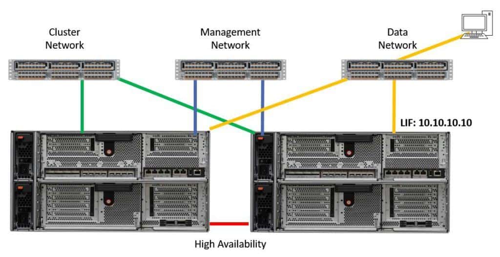
Let's begin by explaining why we need to have broadcast domains. In the diagram below we have the cluster network, the management network, and the data network which are all on separate switches in our example (see the earlier tutorial for an explanation of the network types). The networks are physically separate.

We have a NAS logical interface (LIF) with the IP address 10.10.10.10 and it's homed on the physical interface over on the right. The diagram also shows a client on the data network which is accessing data over that LIF.
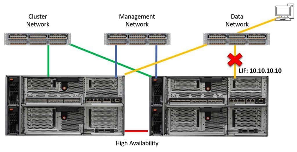
Let’s say we have a failure. Either the data network switch, the network cable, the physical port, or the node itself fails.

Network Failure
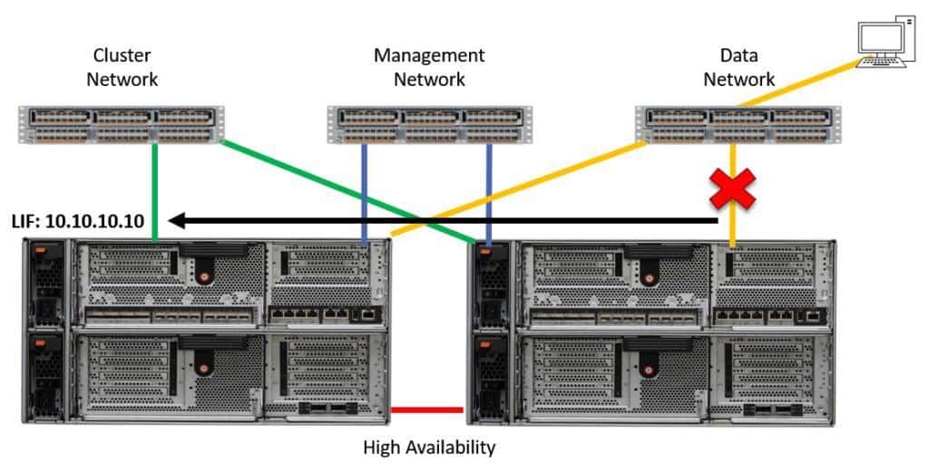
The storage system will detect the failure and automatically fail the LIF over to a different port. The example below shows what could happen if we didn't have Broadcast Domains. The LIF has failed over to the port on the far left, which is on the cluster network.

LIF Failover
At first glance, this looks good because the LIF has failed over to a different physical port. What’s not good is that the port is part of a separate physical network. The client doesn't have any connectivity to the physical port on the cluster network so it's going to lose connectivity to 10.10.10.10 and its data.
It's critical that when a LIF moves to another physical port, clients have the same connectivity to that new port. The client needs to have physical access to the switch which that port is cabled to. We also need to make sure that the VLAN the LIF was originally in is available on the port that it has moved over to.
NetApp Broadcast Domains
It's essential to ensure that if a LIF fails over to another physical port, clients will still have connectivity to that LIF. Broadcast Domains are there to ensure this. Physical, interface group or VLAN ports with the same connectivity (meaning in the same layer 2 network) should be placed in the same broadcast domain.
Ports with different connectivity should be placed in different broadcast domains. Failover groups are automatically set up on the NetApp system based on your broadcast domains.
You specify a home node and port when you create a LIF. The rule is that a LIF can only failover to another port in the same broadcast domain. Because we ensure that the physical ports in our broadcast domains have the same connectivity as each other, clients will still have connectivity in the event of a failover.
NetApp Failover Groups
A failover group is created automatically each time a broadcast domain is created. The name of the failover group is set to be the same as the broadcast domain. A port can only be assigned to one broadcast domain.
As ports are added to or removed from the broadcast domain, the same operation is automatically performed on the associated failover group, so they essentially sync with each other. The ports in the broadcast domain are always mirrored to the failover group.
Failover groups only apply to NAS protocols. Multipathing provides redundancy for SAN protocols. With NAS protocols, a client connects to a particular IP address. If the physical port which that IP address is homed on goes down, we need to make that same IP address move to a different port so the client will still have connectivity to it.
SAN protocols work differently. When using SAN protocols the client will discover it can reach its storage through multiple different IP addresses. The client has intelligence and therefore knows about those different paths.
If one of the paths goes down, it will automatically failover to a different path. We don't need to move IP addresses for redundancy when using SAN protocols.
Default IPspaces, Broadcast Domains, and Failover Groups
Now let's consider our default IPspace, broadcast domains, and failover groups. A broadcast domain resides in an IPspace. Ports are added to broadcast domains, not to the IPspace. There is also a matching failover group for every broadcast domain.
During cluster initialization (the initial setup) the system creates two default IPspaces, broadcast domains, and failover groups. One for the cluster network ports, and another one named Default which all other ports go in. All data and management ports are in the default broadcast domain by default.
This comes with some implications. If you are using separate data and management networks, this needs to be changed because, by default, all your data and management LIFs can fail over to the same ports. If you've got separate switches for management and data then you need to have separate broadcast domains for them as well.
Also, if you are using shared switches for data and management but you've got different VLANs for data and management, you are going to need to make sure that you are trunking both the data and the management VLANs down to those physical ports if you're going to leave this as default. If you've got separate dedicated ports for data and management then, again, you're going to need to have separate broadcast domains for them as well.
The cluster broadcast domain contains ports that are in the cluster IP space. All cluster ports are in the cluster broadcast domain by default. Our cluster interconnect network needs to have a separate dedicated network, otherwise, it's not a configuration supported by Netapp.
The default setup for the cluster broadcast domain is always going to be fine so don't change it. Just check it when you set up the system to make sure that it is configured correctly.
Custom Failover Groups
As well as ensuring that clients still have connectivity to a LIF in the case that it fails over to another physical port, we may also want to ensure that the LIF fails over to a port with the same speed setting.
This would ensure that clients will continue to get the same performance. As an example, if a LIF is normally homed on a 10Gbit Ethernet port, we don't want it to failover to a 1Gbit Ethernet port. We’d want to ensure it fails over to another 10Gbit port. We can configure custom failover groups to make sure that happens.
Another reason we might want to configure custom failover groups is if we want a LIF to only failover to a subset of the ports in a broadcast domain.
You can configure the members of the failover group and the failover policy.
Failover Policies
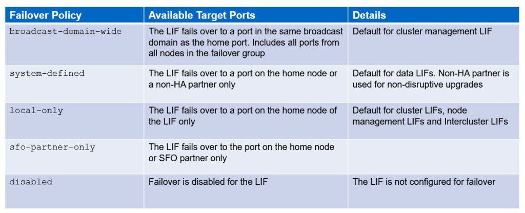
Let's take a look at those failover policies. There are five different policies. The first one is “Broadcast domain wide”. This ensures the LIF fails over to a port in the same broadcast domain as the home port. That includes all ports from all nodes in the failover group. This is the default setup for the cluster management LIF, meaning the LIF we use for cluster wide management can failover to any management port in the cluster.
The next failover policy we have is “System defined”. With this, the LIF fails over to a port under the home node or non-HA partner only. This is the default for our data LIFs that are being used for client data access. The non-HA partner is used for non-disruptive upgrades. That's why it fails over to a port on the home node or a non-HA partner.
The next failover policy that we have is “Local only”. Using “Local Only”, the LIF fails over to a port under the home node of the LIF only. This is the default for cluster LIFs, node management LIFs and inter-cluster LIFs. Only those LIF types are specific to an individual node, so we need to make sure that if there is a failover, the LIF fails over to the same node.
The next failover policy is “SFO partner only”. This causes the LIF to failover to the port under the home node or SFO partner only. The final policy is “Disabled”, which is self-explanatory. This disables failover for the LIF. These last two are not normally used.
With regard to the failover policy, typically we want to leave everything as it is by default. As long as our broadcast domains are configured correctly and we make sure when LIFs do failover, they failover to another port that clients have got connectivity to, then everything should be fine.
The only common reason for deviating from the default is if you've got interfaces with different speeds (e.g. both 1Gbit Ethernet and 10Gbit Ethernet) and you want to configure custom failover groups to make sure that LIFs always fail over to another port of the same speed. Other than that, we would normally leave the defaults.
Do however make sure that you check your setup after you've set up your cluster. You don't want to have misconfigured broadcast domains or failover groups and the first time you find out about it is when you have a failure and your clients can't connect to their data anymore. You want to make sure that everything is configured correctly from the start so you don't run into any of those types of problems.

Failover Policies
Broadcast Domains Configuration Example
Finally, let's have a look at how we might configure our broadcast domains and failover groups.

Configuration Example
Here we've got two SVMs: an SVM for DeptA and an SVM for DeptB. DeptA is using the 10.10.10.x subnet. We've got the address .10 on a LIF on controller 1 and we've got the address .11 on a LIF on controller 2. The switch ports they are plugged into have both been configured as members of VLAN 10 on the switch. We don’t have to configure VLANs on the storage system in this case.
We have a similar configuration for the DeptB SVM. It’s using the sub-net 192.168.20.x. We've got a LIF on node 1 using the address .10 and a different LIF on node 2 using .11. The switch ports they are plugged into are configured as part of VLAN 20.
In this example, we have put ports e0a from both nodes into a broadcast domain for DeptA and we have put ports e1a from both nodes into a broadcast domain for the DeptB SVM. This makes sure that if any LIF has to failover, it will failover to a port that has the same connectivity so clients will still be able to access their data.
NetApp Broadcast Domains and Failover Groups Configuration Example
This configuration example is an excerpt from my ‘NetApp ONTAP 9 Complete’ course. Full configuration examples using both the CLI and System Manager GUI are available in the course.
Want to practice this configuration for free on your laptop? Download your free step-by-step guide ‘How to Build a NetApp ONTAP Lab for Free’

- Verify e0a and e0b are being used as the cluster ports on both nodes.
cluster1::> network port show
Node: cluster1-01
Speed(Mbps) Health
Port IPspace Broadcast Domain Link MTU Admin/Oper Status
--------- ------------ ---------------- ---- ---- ----------- --------
e0a Cluster Cluster up 1500 auto/1000 healthy
e0b Cluster Cluster up 1500 auto/1000 healthy
e0c Default Default up 1500 auto/1000 healthy
e0d Default Default up 1500 auto/1000 healthy
e0e Default Default up 1500 auto/1000 healthy
e0f Default Default up 1500 auto/1000 healthy
Node: cluster1-02
Speed(Mbps) Health
Port IPspace Broadcast Domain Link MTU Admin/Oper Status
--------- ------------ ---------------- ---- ---- ----------- --------
e0a Cluster Cluster up 1500 auto/1000 healthy
e0b Cluster Cluster up 1500 auto/1000 healthy
e0c Default Default up 1500 auto/1000 healthy
e0d Default Default up 1500 auto/1000 healthy
e0e Default Default up 1500 auto/1000 healthy
e0f Default Default up 1500 auto/1000 healthy
12 entries were displayed.
- Verify both nodes have a cluster LIF homed on both of their cluster ports.
cluster1::> network interface show
Logical Status Network Current Current Is
Vserver Interface Admin/Oper Address/Mask Node Port Home
----------- ---------- ---------- ------------------ ------------- ------- ----
Cluster
cluster1-01_clus1
up/up 169.254.148.29/16 cluster1-01 e0a true
cluster1-01_clus2
up/up 169.254.148.39/16 cluster1-01 e0b true
cluster1-02_clus1
up/up 169.254.23.26/16 cluster1-02 e0a true
cluster1-02_clus2
up/up 169.254.23.36/16 cluster1-02 e0b true
cluster1
cluster1-01_mgmt1
up/up 172.23.1.12/24 cluster1-01 e0c true
cluster1-02_mgmt1
up/up 172.23.1.13/24 cluster1-02 e0c true
cluster_mgmt up/up 172.23.1.11/24 cluster1-01 e0c true
7 entries were displayed.
- What is the failover policy on the cluster LIFs?
cluster1::> network interface show -vserver Cluster -lif cluster1-01_clus1
Vserver Name: Cluster
Logical Interface Name: cluster1-01_clus1
Role: cluster
Data Protocol: none
Network Address: 169.254.148.29
Netmask: 255.255.0.0
Bits in the Netmask: 16
Is VIP LIF: false
Subnet Name: -
Home Node: cluster1-01
Home Port: e0a
Current Node: cluster1-01
Current Port: e0a
Operational Status: up
Extended Status: -
Is Home: true
Administrative Status: up
Failover Policy: local-only
Firewall Policy:
Auto Revert: true
Fully Qualified DNS Zone Name: none
DNS Query Listen Enable: false
Failover Group Name: Cluster
FCP WWPN: -
Address family: ipv4
Comment: -
IPspace of LIF: Cluster
Is Dynamic DNS Update Enabled?: -
Service Policy: -
Service List: -
Probe-port for Azure ILB: -
The failover policy is ‘local-only’. If a port fails then its LIF will failover to the other cluster port on the node.
- Which ports are currently being used for management?
cluster1::> network interface show
Logical Status Network Current Current Is
Vserver Interface Admin/Oper Address/Mask Node Port Home
----------- ---------- ---------- ------------------ ------------- ------- ----
Cluster
cluster1-01_clus1
up/up 169.254.148.29/16 cluster1-01 e0a true
cluster1-01_clus2
up/up 169.254.148.39/16 cluster1-01 e0b true
cluster1-02_clus1
up/up 169.254.23.26/16 cluster1-02 e0a true
cluster1-02_clus2
up/up 169.254.23.36/16 cluster1-02 e0b true
cluster1
cluster1-01_mgmt1
up/up 172.23.1.12/24 cluster1-01 e0c true
cluster1-02_mgmt1
up/up 172.23.1.13/24 cluster1-02 e0c true
cluster_mgmt up/up 172.23.1.11/24 cluster1-01 e0c true
7 entries were displayed.
Port e0c on both nodes is being used for management.
- Which Broadcast Domain are the management ports in?
cluster1::> network port show
Node: cluster1-01
Speed(Mbps) Health
Port IPspace Broadcast Domain Link MTU Admin/Oper Status
--------- ------------ ---------------- ---- ---- ----------- --------
e0a Cluster Cluster up 1500 auto/1000 healthy
e0b Cluster Cluster up 1500 auto/1000 healthy
e0c Default Default up 1500 auto/1000 healthy
e0d Default Default up 1500 auto/1000 healthy
e0e Default Default up 1500 auto/1000 healthy
e0f Default Default up 1500 auto/1000 healthy
Node: cluster1-02
Speed(Mbps) Health
Port IPspace Broadcast Domain Link MTU Admin/Oper Status
--------- ------------ ---------------- ---- ---- ----------- --------
e0a Cluster Cluster up 1500 auto/1000 healthy
e0b Cluster Cluster up 1500 auto/1000 healthy
e0c Default Default up 1500 auto/1000 healthy
e0d Default Default up 1500 auto/1000 healthy
e0e Default Default up 1500 auto/1000 healthy
e0f Default Default up 1500 auto/1000 healthy
12 entries were displayed.
The management ports are in the Default Broadcast Domain.
- What is the failover policy on the node management LIFs?
cluster1::> network interface show -vserver cluster1 -lif cluster1-01_mgmt1
Vserver Name: cluster1
Logical Interface Name: cluster1-01_mgmt1
Role: node-mgmt
Data Protocol: none
Network Address: 172.23.1.12
Netmask: 255.255.255.0
Bits in the Netmask: 24
Is VIP LIF: false
Subnet Name: -
Home Node: cluster1-01
Home Port: e0c
Current Node: cluster1-01
Current Port: e0c
Operational Status: up
Extended Status: -
Is Home: true
Administrative Status: up
Failover Policy: local-only
Firewall Policy: mgmt
Auto Revert: true
Fully Qualified DNS Zone Name: none
DNS Query Listen Enable: false
Failover Group Name: Default
FCP WWPN: -
Address family: ipv4
Comment: -
IPspace of LIF: Default
Is Dynamic DNS Update Enabled?: -
Service Policy: -
Service List: -
Probe-port for Azure ILB: -
The failover policy is ‘local-only’. If an e0c port fails then its node management LIF will failover to another port in the Default Broadcast Domain on the same node.
- What is the failover policy on the cluster management LIF?
cluster1::> network interface show -vserver cluster1 -lif cluster_mgmt
Vserver Name: cluster1
Logical Interface Name: cluster_mgmt
Role: cluster-mgmt
Data Protocol: none
Network Address: 172.23.1.11
Netmask: 255.255.255.0
Bits in the Netmask: 24
Is VIP LIF: false
Subnet Name: -
Home Node: cluster1-01
Home Port: e0c
Current Node: cluster1-01
Current Port: e0c
Operational Status: up
Extended Status: -
Is Home: true
Administrative Status: up
Failover Policy: broadcast-domain-wide
Firewall Policy: mgmt
Auto Revert: false
Fully Qualified DNS Zone Name: none
DNS Query Listen Enable: false
Failover Group Name: Default
FCP WWPN: -
Address family: ipv4
Comment: -
IPspace of LIF: Default
Is Dynamic DNS Update Enabled?: -
Service Policy: -
Service List: -
Probe-port for Azure ILB: -
The failover policy is ‘broadcast-domain-wide’. If the underlying port fails then the cluster management LIF will failover to another port in the Default Broadcast Domain on either node.
- Look at the network topology diagram. Can you see a problem with the current failover settings for the management LIFs?
Yes. If an e0c port fails the management LIF can failover to port e0d, e0e, or e0f, but only ports e0c and e0f are connected to the management network.
- The first job is to fix the Broadcast Domain so failover works correctly for the management LIFs. Reconfigure the ‘Default’ Broadcast Domain so it is named ‘Management’ and contains only the management ports on both nodes.
cluster1::> network port broadcast-domain rename -ipspace Default -broadcast-domain Default -new-name Management
cluster1::> network port broadcast-domain remove-ports -ipspace Default -broadcast-domain Management -ports cluster1-01:e0d
cluster1::> network port broadcast-domain remove-ports -ipspace Default -broadcast-domain Management -ports cluster1-01:e0e
cluster1::> network port broadcast-domain remove-ports -ipspace Default -broadcast-domain Management -ports cluster1-02:e0d
cluster1::> network port broadcast-domain remove-ports -ipspace Default -broadcast-domain Management -ports cluster1-02:e0e
- Verify your changes.
cluster1::> network port broadcast-domain show
IPspace Broadcast Update
Name Domain Name MTU Port List Status Details
------- ----------- ------ ----------------------------- ----------
Cluster Cluster 1500
cluster1-01:e0a complete
cluster1-01:e0b complete
cluster1-02:e0a complete
cluster1-02:e0b complete
Default Management 1500
cluster1-01:e0c complete
cluster1-01:e0f complete
cluster1-02:e0c complete
cluster1-02:e0f complete
2 entries were displayed.
- Verify there is a matching ‘Management’ Failover Group which contains the correct ports.
cluster1::> network interface failover-groups show
Failover
Vserver Group Targets
---------------- ---------------- ----------------------------------
Cluster
Cluster
cluster1-01:e0a, cluster1-01:e0b,
cluster1-02:e0a, cluster1-02:e0b
cluster1
Management
cluster1-01:e0c, cluster1-01:e0f,
cluster1-02:e0c, cluster1-02:e0f
2 entries were displayed.
Additional Resources
Configuring Broadcast Domains from NetApp.
Check out the rest of our NetApp networking tutorial series:
Part 1: NetApp Interface Groups
Part 3: NetApp Logical Interfaces (LIFs)
And more coming soon...
Click Here to get my 'NetApp ONTAP 9 Storage Complete' training course.

Text by Alex Papas, Technical Writer at www.flackbox.com
Alex has been working with Data Center technologies for over 20 years. Currently he is the Network Lead for Costa, one of the largest agricultural companies in Australia. When he’s not knee deep in technology you can find Alex performing with his band 2am