In this NetApp training tutorial, we will cover NetApp SAN implementation on clustered ONTAP. Scroll down for the video and also text tutorial.
NetApp SAN Implementation Video Tutorial
Randy Johnson

The concepts, explanations, and applications to real world scenarios are exceptional. The hands-on labs reinforce the learning, and are actually better than the vendors’ labs.
I always feel fully engaged and fully oriented to the teaching. There has never been a time when I was scratching my head or not understanding the explanations or examples. And I can take the labs and examples and apply them directly in real environments.
What is a Storage Area Network (SAN)?
Storage Area Network (SAN) provides block-level access to storage resources. The data is stored and accessed in blocks that are stored in LUNs. It allows the clients to manage the allocated space on the storage system similar to a local hard drive.
What is SAN Storage Used For?
SANs are usually used to support databases and performance-sensitive applications due to its speed, availability, and resiliency.
Since SAN also offers a high throughput and low latency, it is commonly used for business-critical applications and other high-performance applications such as:
- Databases
- Virtualization Deployments
- Virtual Desktop Infrastructure (VDI) Environments
- SAP, ERP, and CRM Environments
NetApp SAN Implementation - LUNs
Let’s start with some terminology. For SAN protocols, the storage system is referred to as the target and the client is known as the initiator. A LUN (Logical Unit Number) is a logical representation of a disk which is presented by the target to the initiator.
SAN protocols provide low-level block access to the storage. The LUN is a logical representation of a disk and the initiator can use it exactly the same way it would use a local hard disk installed in its chassis.
LUNs are specific to the SAN protocols (FC, FCoE, and iSCSI), they are not used for NAS.
In NetApp storage, the LUN is located in either a volume or a qtree. Best practice is to have a dedicated volume or qtree for each LUN. Do not put multiple LUNs in the same qtree or volume (unless each LUN is in a separate dedicated qtree in a volume.)
iSCSI Configuration
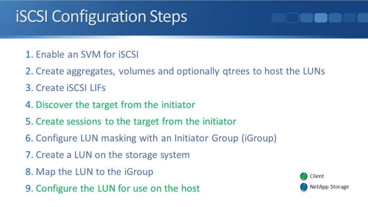
The steps written in green font on the slide above are to be configured on the iSCSI client, while the rest are configured on the NetApp storage system.
iSCSI CHAP Authentication
Configuring CHAP authentication for iSCSI is optional. For Fibre Channel, initiator access to the SAN is controlled through zoning on our switches, so it is inherently secure.
Ethernet switches however do not support zoning. This is why it is recommended to use CHAP authentication between the initiator and the target. On one-way CHAP, the target only authenticates the initiator while with mutual CHAP, it’s two-way where the initiator also authenticates the target.
Fibre Channel and FCoE (Fibre Channel over Ethernet)
Both Fibre Channel and FCoE use the Fibre Channel Protocol (FCP) and work in exactly the same way. FCoE is Fibre Channel, just encapsulated in an Ethernet header so that it can run over Ethernet networks.
Both are configured as ‘Fibre Channel’ on NetApp storage, there is not a separate page on the System Manager GUI for FCoE.
They both use World Wide Port Name WWPNs for the addressing on the initiators and the targets.
The WWPNs are assigned to Fibre Channel LIFs on the NetApp storage system. Fibre Channel LIFs can be homed on UTA2 (Unified Target Adapter) ports, which can be configured as either native Fibre Channel, or as 10Gb CNA (Converged Network Adapter) ports with FCoE support.
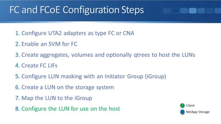
To set up FC or FCoE, first, configure the UTA2 adapters as either type Fibre Channel or type CNA. This step isn’t required for iSCSI since it always uses Ethernet adapters. Other than that, the configuration steps are very similar for iSCSI and FC/FCoE.
The next task is to enable the SAN protocol on the SVM (Storage Virtual Machine). SVMs are how secure multi-tenancy is enabled in ONTAP. Different SVMs appear as separate storage systems to clients.
The World Wide Node Name WWNN (FC/FCoE) or iSCSI Qualified Name IQN identifies the storage system as a whole. For the SAN protocols, different SVMs will have different WWNNs or IQNs so that they appear as separate systems.
After we tie the LUN to the initiator group with a mapping, we don’t need to discover the target from the initiator because this is done automatically within the Fibre Channel Protocol using the fabric login process.
Once the NetApp side is done, go to the client and configure its LUN access using its multipath software.
SAN Logical Interfaces (LIFs)
The system as a whole is identified by WWPN (FC or FCoE) or iQN (iSCSI). Individual ports on the storage system in the SVM are identified by WWPN, if it's Fibre Channel or FCoE, or IP address if it's SCSI.
The WWPNs and IP addresses are not applied directly to physical ports, they're applied to logical interfaces. This is the same as for our NAS protocols.
Separation of the physical port and logical interface provides flexibility which allows multiple LIFs to share the same underlying physical port. SAN LIFs support either Fibre Channel, FCoE, or iSCSI. FC LIFs have WWPNs, iSCSI LIFs have IP addresses.
Clients using NAS protocols cannot use SAN LIFs to access their data. SAN LIFs can, however, share underlying physical interfaces with NAS LIFs. So on the same physical port, we could have a NAS LIF that's being used for NFS, and a SAN LIF that’s being used for iSCSI for example. The different LIFs on the same physical port would have different IP addresses.
SAN LIFs are assigned a home node and port just like the NAS LIFs. The only difference is, SAN LIFs don’t failover like NAS LIFs do. SAN protocols leverage multipathing intelligence on the clients. If a SAN LIF fails, the clients know the other paths it can take to get to its LUN, so there is no need for the LIF to failover to another port.
SAN LIFs can be migrated from their home port over to different ports or nodes within an SVM. So they're not going to automatically failover but as an administrator, we can manually move a LIF to a different port.
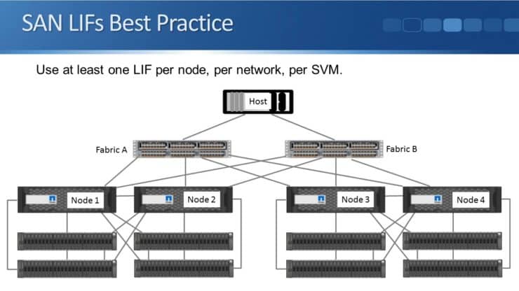
Best practice is to create at least one LIF per node, per network, per SVM. The example below shows eight paths from the hosts to the storage, with eight LIFs on the storage, two on each node.
Additional Resources