In this NetApp training tutorial, I will explain NetApp Subnets. This is the sixth post in our NetApp networking video tutorial series. Links for the other videos in the series are at the bottom of the page. Scroll down for the video and also text tutorial.
NetApp Subnets Video Tutorial
Kyung Pastino

I took Netapp ONTAP classroom training about a month ago and then watched your tutorials 3 times each. Your tutorials were much better than the class. I took the test last week and passed it. I don’t think I could have done that without your tutorials. Thank you so much!!!
NetApp Subnets
NetApp Subnets are another one of the newer networking features that were introduced in Data OnTap version 8.3. Subnets allow the allocation of specific blocks or pools of IP addresses and help make Logical Interface (LIF) creation easier.
A Subnet is created within a Broadcast Domain. You specify both the Broadcast Domain and Default Gateway when you create a Subnet.
When you create a LIF, you assign an IP address. This can either be done the old way where you manually specify the IP address each time you create a LIF, or you can configure the LIF to be automatically assigned the next available IP from the range of addresses in your Subnet.
The reason that we have Subnets is really just for convenience. If we use a Subnet when we assign the IP to our LIF it ensures that we don’t accidentally type in the wrong address. It also saves us from having to specify the Broadcast Domain and the Default Gateway, as well as having to configure routing separately. It essentially makes it easier to create our LIF.
Here's an example of how we would configure our Subnets:
NetApp Subnets Example
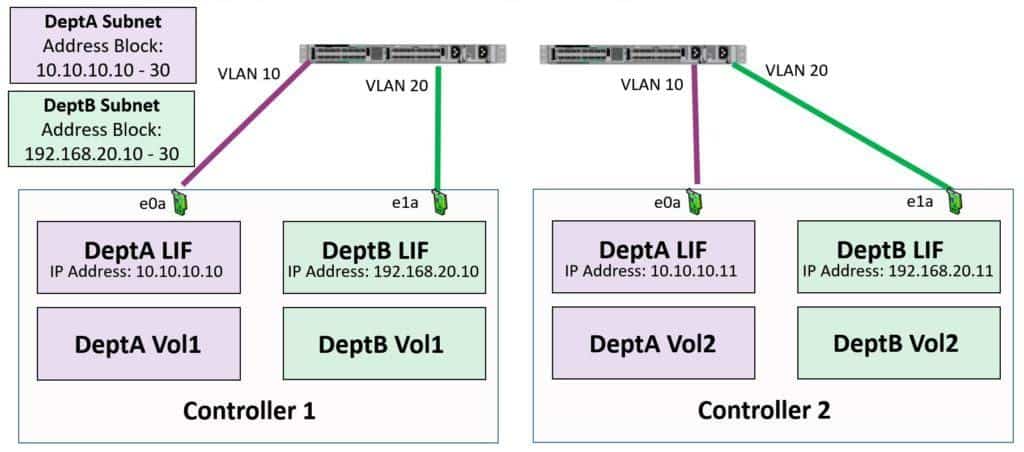
We have a DeptA SVM and its LIFs are using Subnet 10.10.10.x. We’ve also got a DeptB SVM and its LIFs are using the Subnet 192.168.20.x.
We create a Subnet for DeptA, specifying a block of IP addresses from 10.10.10.10 to 10.10.10.30. When we create our first LIF for DeptA, it will automatically get IP address 10.10.10.10. The second LIF will get 10.10.10.11, the next one would get 10.10.10.12, and so on.
We do the same thing for DeptB using the 192.168.20 Subnet, specifying an address range from 192.168.20.10 to 192.168.20.30. DeptB's first LIF will get the IP address 192.168.20.10, the next one will get 192.168.20.11, and so on.
We could create a LIF with a specific IP address (such as 192.168.20.50) if required. We would just specify the IP address manually when creating that LIF rather than letting the system automatically assign one from the specified block of IP addresses.
Static Routes
Although this is not directly specific to Subnets, this is also a good time to talk about static routes. Each SVM has its own routing table and default gateways are created when you configure a Subnet. Although this will normally be all you need to handle the routing requirements for an SVM, static routes can also be configured.
The diagram below shows an example of when you would need to do so:
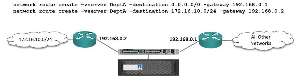
NetApp Static Routes
We've got two routers in the same 192.168.0.0/24 subnet. The first (192.168.0.2) is a gateway for the 172.16.10.x subnet and the second (192.168.0.1) is the router for all other networks.
In this case, we need to configure static routes.
To do this we use the command “network route create -vserver DeptA -destination 0.0.0.0/0” and configure the static default route for gateway 192.168.0.1.
We then use the same command, again for vserver DeptA, but this time makes the destination 172.16.10.0/24 and the gateway is 192.168.0.2.
What will now happen is all traffic will go out to Gateway 192.168.0.1 unless it's for the 172.16.10.x network, in which case it will get to 192.168.0.2.
In real-world deployments, it's highly unlikely you would ever need to do this. In most cases, you will have just one router for a particular Subnet, but if you do have this kind of unusual configuration, it is supported by NetApp.
NetApp Subnets Networking Tutorial Configuration Example
This configuration example is an excerpt from my ‘NetApp ONTAP 9 Complete’ course. Full configuration examples using both the CLI and System Manager GUI are available in the course.
Want to practice this configuration for free on your laptop? Download your free step-by-step guide ‘How to Build a NetApp ONTAP Lab for Free’

- Create a Subnet for DeptA using IP addresses 172.23.14.21 to 172.23.14.40. The gateway is at 172.23.14.254
cluster1::> network subnet create -ipspace Default -subnet-name DeptA -broadcast-domain DeptA -subnet 172.23.14.0/255.255.255.0 -gateway 172.23.14.254 -ip-ranges 172.23.14.21-172.23.14.40
- Create a Subnet for DeptB using IP addresses 172.23.15.21 to 172.23.15.40. The gateway is at 172.23.15.254
cluster1::> network subnet create -ipspace Default -subnet-name DeptB -broadcast-domain DeptB -subnet 172.23.15.0/255.255.255.0 -gateway 172.23.15.254 -ip-ranges 172.23.15.21-172.23.15.40
- Verify the Subnets.
cluster1::> network subnet show
IPspace: Default
Subnet Broadcast Avail/
Name Subnet Domain Gateway Total Ranges
--------- ---------------- --------- --------------- --------- ---------------
DeptA 172.23.14.0/24 DeptA 172.23.14.254 20/20 172.23.14.21-172.23.14.40
DeptB 172.23.15.0/24 DeptB 172.23.15.254 20/20 172.23.15.21-172.23.15.40
2 entries were displayed.
- Create Logical Interfaces on the VLAN 14 interfaces on Node 1 and Node 2 for DeptA client data access. The client access protocols in use are NFS and iSCSI. Create separate LIFs for both protocols.
cluster1::> network interface create -vserver DeptA -lif cluster1-01_DeptA_nfs -role data -data-protocol nfs -home-node cluster1-01 -home-port a0a-14 -subnet-name DeptA
cluster1::> network interface create -vserver DeptA -lif cluster1-02_DeptA_nfs -role data -data-protocol nfs -home-node cluster1-02 -home-port a0a-14 -subnet-name DeptA
cluster1::> network interface create -vserver DeptA -lif cluster1-01_DeptA_iscsi -role data -data-protocol iscsi -home-node cluster1-01 -home-port a0a-14 -subnet-name DeptA
cluster1::> network interface create -vserver DeptA -lif cluster1-02_DeptA_iscsi -role data -data-protocol iscsi -home-node cluster1-02 -home-port a0a-14 -subnet-name DeptA
- Create Logical Interfaces on the VLAN 15 interfaces on Node 1 and Node 2 for DeptB client data access. The client access protocols in use are CIFS and iSCSI. Create separate LIFs for both protocols.
cluster1::> network interface create -vserver DeptB -lif cluster1-01_DeptB_cifs -role data -data-protocol cifs -home-node cluster1-01 -home-port a0a-15 -subnet-name DeptB
cluster1::> network interface create -vserver DeptB -lif cluster1-02_DeptB_cifs -role data -data-protocol cifs -home-node cluster1-02 -home-port a0a-15 -subnet-name DeptB
cluster1::> network interface create -vserver DeptB -lif cluster1-01_DeptB_iscsi -role data -data-protocol iscsi -home-node cluster1-01 -home-port a0a-15 -subnet-name DeptB
cluster1::> network interface create -vserver DeptB -lif cluster1-02_DeptB_iscsi -role data -data-protocol iscsi -home-node cluster1-02 -home-port a0a-15 -subnet-name DeptB
- Verify the LIFs.
cluster1::> network interface show
Logical Status Network Current Current Is
Vserver Interface Admin/Oper Address/Mask Node Port Home
----------- ---------- ---------- ------------------ ------------- ------- ----
Cluster
cluster1-01_clus1
up/up 169.254.148.29/16 cluster1-01 e0a true
cluster1-01_clus2
up/up 169.254.148.39/16 cluster1-01 e0b true
cluster1-02_clus1
up/up 169.254.23.26/16 cluster1-02 e0a true
cluster1-02_clus2
up/up 169.254.23.36/16 cluster1-02 e0b true
DeptA
cluster1-01_DeptA_iscsi
up/up 172.23.14.23/24 cluster1-01 a0a-14 true
cluster1-01_DeptA_nfs
up/up 172.23.14.21/24 cluster1-01 a0a-14 true
cluster1-02_DeptA_iscsi
up/up 172.23.14.24/24 cluster1-02 a0a-14 true
cluster1-02_DeptA_nfs
up/up 172.23.14.22/24 cluster1-02 a0a-14 true
DeptB
cluster1-01_DeptB_cifs
up/up 172.23.15.21/24 cluster1-01 a0a-15 true
cluster1-01_DeptB_iscsi
up/up 172.23.15.23/24 cluster1-01 a0a-15 true
cluster1-02_DeptB_cifs
up/up 172.23.15.22/24 cluster1-02 a0a-15 true
cluster1-02_DeptB_iscsi
up/up 172.23.15.24/24 cluster1-02 a0a-15 true
Additional Resources
Configuring Subnets from NetApp.
The "network subnet create" Command
Check out the rest of our NetApp networking tutorial series:
Part 1: NetApp Interface Groups
Part 3: NetApp Logical Interfaces (LIFs)
Part 5: NetApp Broadcast Domains and Failover Groups
And more coming soon...
Click Here to get my 'NetApp ONTAP 9 Storage Complete' training course.

Text by Alex Papas, Technical Writer at www.flackbox.com
Alex has been working with Data Center technologies for over 20 years. Currently he is the Network Lead for Costa, one of the largest agricultural companies in Australia. When he’s not knee deep in technology you can find Alex performing with his band 2am