In this NetApp training tutorial, I will explain the NetApp Interface Groups. Interface Groups enable link aggregation of one or more Ethernet interfaces. This is the first in a series on NetApp networking, you can find links to the other tutorials at the bottom of the page. Scroll down for the video and also text tutorial.
NetApp Interface Groups Video Tutorial

Tejinder Singh Grewal

Excellent course, highly recommended if you want to learn everything about NetApp.
NetApp Interface Groups
NetApp Interface Groups are similar to NIC teaming on a standard server. They can be used to achieve redundancy (and possibly load balancing) for our network ports, links, and switches. NIC teaming bundles multiple physical links into a single logical link with one shared IP address.
If we then have an outage of a port, link or switch then we still have connectivity to the IP address through the surviving path. You can see an example of this in the diagram below:
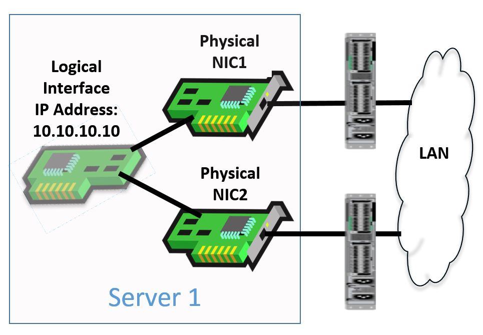
NIC Teaming
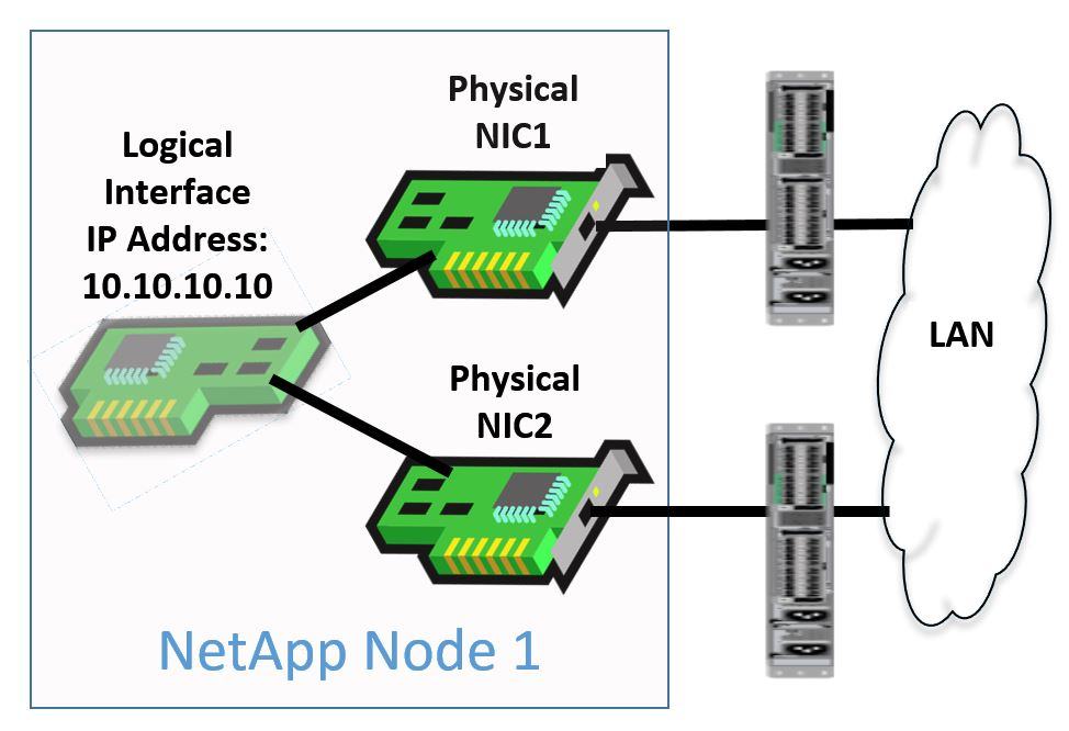
We don't need Interface Groups for physical port redundancy on our NetApp systems. This is because we have Failover Groups that handle it for NAS protocols and Multipathing on the client that handles it for SAN protocols.
I’ll cover Failover Groups and Multipathing in detail in later blog posts. For now, let’s focus on Interface Groups. You’re probably wondering - if Interface Groups aren’t required for redundancy, then why do we have them? I’ll get to that below.
There's a couple of different types of Interface Groups: Single-Mode and Multimode.
Single-Mode NetApp Interface Groups
Single-Mode Interface Groups can be used to provide active/standby redundancy (no load balancing) when the attached LAN switches do not support link aggregation. Single-Mode Interface Groups are not recommended on NetApp systems because the standby interface does not get used unless the active fails.
We can use Failover Groups instead, which provide the same level of redundancy without giving up half of our available bandwidth.
Single-Mode Interface Groups do not need any special configuration on the attached switches. The switches can be configured the same as if they had a normal end-host attached.
NetApp Single-Mode Interface Group
So Single-Mode Interface Groups are not recommended to be used. We can however use Multimode Interface Groups.
NetApp Multimode Interface Groups
Multimode Interface Groups are active/active and provide redundancy and load balancing. They can be used to provide the bandwidth of multiple interfaces to a single IP address. There are two types of Multimode interface: Static (802.3ad) and Dynamic (LACP).
LACP is preferred out of the two as it's the more modern and stable protocol. You would only use Static if the switch has support for that but not for LACP.
Multimode Interface Groups need a matching configuration on both the storage system and the attached switches. The link bundle must be negotiated by both sides for it to come up. The configuration on the switch is known as a Port Channel, EtherChannel, or Link Aggregation (LAG).
If the storage system has a Multimode Interface Group connected to two different switches, then you will need advanced switches (such as the Cisco Nexus) that support Multi-Chassis EtherChannel (MEC). This allows a single port channel to be shared between two different switches.
Effects of NetApp Interface Group Configuration
We look at the effects of configuring Interface Groups in the diagram below.
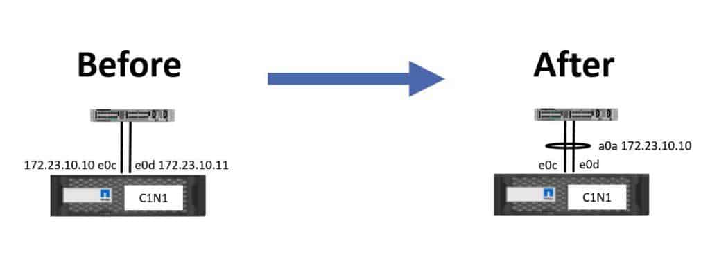
Effects of NetApp Interface Group Configuration
With the ‘before’ example on the left, we haven't configured an Interface Group. There are two interfaces, e0c and e0d. In our example these are 1Gb Ethernet interfaces.
We configure a Logical Interface with IP address 172.23.10.10 and place it on e0c as its home port, and then we configure another Logical Interface with IP address 172.23.10.11 and put that on e0d. In this case both IP addresses will have 1Gb worth of bandwidth available to them.
Now let’s consider the case of ‘after’ on the right of the diagram, where we have configured an Interface Group. We've got the same two 1Gb Ethernet physical ports again, e0c and e0d, but now we bundle them into an Interface Group. Notice here we've named it a0a.
You can actually call the Interface Group anything you want but the standard naming convention is to prefix it with an ‘a’ for ‘aggregate’.
We’ve done that and have now got a single Logical Interface with IP address 172.23.10.10. The Logical Interface can no longer be placed on e0c or e0d as its home port because they are members of an Interface Group now. We could only put it on interface a0a.
The benefit we get from doing this is that now we've got a single IP address which has 2Gb worth of bandwidth rather than just one, and the IP address will remain available if a port or cable fails.
Supported Configurations
Next, we’ll take a look at supported configurations.
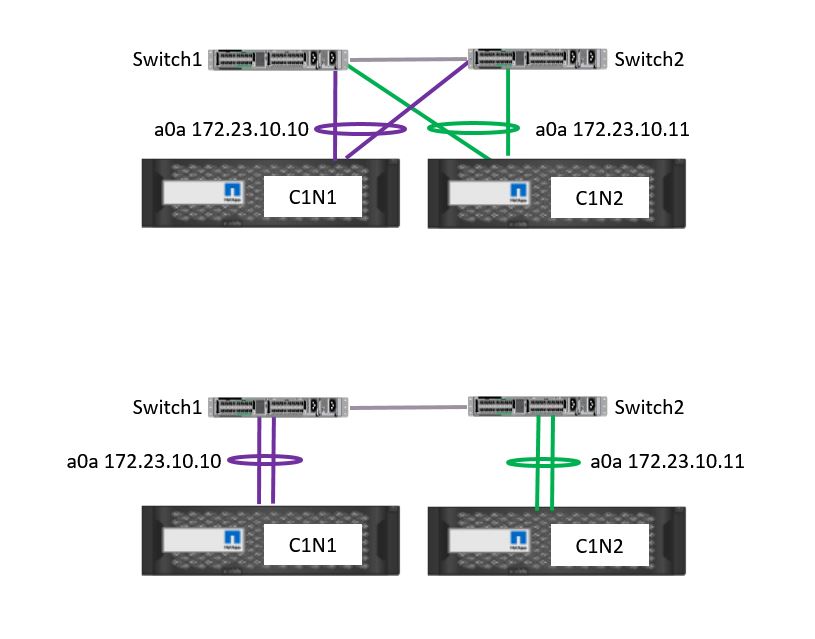
NetApp Interface Group Supported Configurations
In the top example in the diagram, we have an Interface Group on Controller 1 which is connected to two different switches. We repeat this for Controller 2. We have two Interface Groups - a0a on Controller 1, and a0a on Controller 2.
We’ve homed a Logical Interface with IP address 172.23.10.10 on Controller 1 a0a, and we’ve homed a Logical Interface with IP address 172.23.10.10 on Controller 1 a0a.
The top example would require the attached switches to support Multi-Chassis Etherchannel. The example topology on the bottom of the diagram is also supported. Again, Controller 1 and Controller 2 have both got Interface Groups configured with two physical ports in each. Here, however, Controller 1 is connected to a single switch and Controller 2 is also connected to a single switch.
For a normal Windows server we would prefer the top option because that gives redundancy for the switches whereas the bottom option does not. With NetApp we have Failover Groups however so the second option is equally viable, we will still have redundancy.
If we implement the top option and the switch on the left fails then our clients can still reach 172.23.10.10 because of the other link in our Interface Group.
If we implement the bottom option and the switch fails then our clients can still reach 172.23.10.10 because our Failover Group will fail it over to port a0a on Controller 2.
NetApp Interface Groups Configuration Example
This configuration example is an excerpt from my ‘NetApp ONTAP 9 Complete’ course. Full configuration examples using both the CLI and System Manager GUI are available in the course.
Want to practice this configuration for free on your laptop? Download your free step-by-step guide ‘How to Build a NetApp ONTAP Lab for Free’

- Verify ports e0d and e0e on both nodes are available to be added to Interface Groups.
cluster1::> network port show
Node: cluster1-01
Port IPspace Broadcast Domain Link MTU Admin/Oper Status
--------- ------------ ---------------- ---- ---- ----------- ------
e0a Cluster Cluster up 1500 auto/1000 healthy
e0b Cluster Cluster up 1500 auto/1000 healthy
e0c Default Management up 1500 auto/1000 healthy
e0d Default - up 1500 auto/1000 healthy
e0e Default - up 1500 auto/1000 healthy
e0f Default Management up 1500 auto/1000 healthy
Node: cluster1-02
Port IPspace Broadcast Domain Link MTU Admin/Oper Status
--------- ------------ ---------------- ---- ---- ----------- --------
e0a Cluster Cluster up 1500 auto/1000 healthy
e0b Cluster Cluster up 1500 auto/1000 healthy
e0c Default Management up 1500 auto/1000 healthy
e0d Default - up 1500 auto/1000 healthy
e0e Default - up 1500 auto/1000 healthy
e0f Default Management up 1500 auto/1000 healthy
cluster1::> network interface show
Logical Status Network Current Current Is
Vserver Interface Admin/Oper Address/Mask Node Port Home
----------- ---------- ---------- ------------------ ------------- ------- ----
Cluster
cluster1-01_clus1
up/up 169.254.148.29/16 cluster1-01 e0a true
cluster1-01_clus2
up/up 169.254.148.39/16 cluster1-01 e0b true
cluster1-02_clus1
up/up 169.254.23.26/16 cluster1-02 e0a true
cluster1-02_clus2
up/up 169.254.23.36/16 cluster1-02 e0b true
cluster1
cluster1-01_mgmt1
up/up 172.23.1.12/24 cluster1-01 e0c true
cluster1-02_mgmt1
up/up 172.23.1.13/24 cluster1-02 e0c true
cluster_mgmt up/up 172.23.1.11/24 cluster1-01 e0c true
7 entries were displayed.
Ports e0d and e0e on both nodes are not members of a Broadcast Domain and do not have any Logical Interfaces on them.
- Create singlemode Interface Groups using ports e0d and e0e on both nodes. Use IP distribution and the default settings.
cluster1::> network port ifgrp create -node cluster1-01 -ifgrp a0a -distr-func ip -mode singlemode
cluster1::> network port ifgrp add-port -node cluster1-01 -ifgrp a0a -port e0d
cluster1::> network port ifgrp add-port -node cluster1-01 -ifgrp a0a -port e0e
cluster1::> network port ifgrp create -node cluster1-02 -ifgrp a0a -distr-func ip -mode singlemode
cluster1::> network port ifgrp add-port -node cluster1-02 -ifgrp a0a -port e0d
cluster1::> network port ifgrp add-port -node cluster1-02 -ifgrp a0a -port e0e
- Verify your configuration.
cluster1::> network port ifgrp show
Port Distribution Active
Node IfGrp Function MAC Address Ports Ports
-------- ---------- ------------ ----------------- ------- ---------
cluster1-01
a0a ip 02:0c:29:6f:94:1d partial e0d, e0e
cluster1-02
a0a ip 02:0c:29:a6:17:1a partial e0d, e0e
2 entries were displayed.
Additional Resources
How Interface Groups Work in ONTAP
Check out the rest of our NetApp networking tutorial series:
Part 3: NetApp Logical Interfaces (LIFs)
Part 5: NetApp Broadcast Domains and Failover Groups
And more coming soon...
Click Here to get my 'NetApp ONTAP 9 Storage Complete' training course.