In this NetApp training tutorial, I will explain how Flash Pool aggregates on NetApp ONTAP storage systems work. Flash Pool is a NetApp VST (Virtual Storage Tier) caching technology. Scroll down for the video and also text tutorial.
Flash Pool – NetApp VST (Virtual Storage Tier) Video Tutorial

Joseph Dermody

I began working for NetApp in 2007, they should make your course a mandatory prerequisite for all of their engineers. The lectures are concise and to the point and the extensive catalog of content you provide is unrivaled.
Nothing I’ve come across will prepare someone for a NetApp certification like your one-stop-shop course.
This post is the final part of a three part series where I explain how NetApp FAS storage systems handle reads and writes. You can read the previous parts by clicking on the links below:
Part One: NetApp WAFL, NVRAM and the System Memory Cache
Part Two: Flash Cache – NetApp VST (Virtual Storage Tier)
Flash Pool VST
A Flash Pool aggregate is made up of traditional HDD spinning disk hard drives, which are fronted by a cache of SSD drives to improve performance.
In the diagram below we have an existing aggregate which is made up of HDDs.
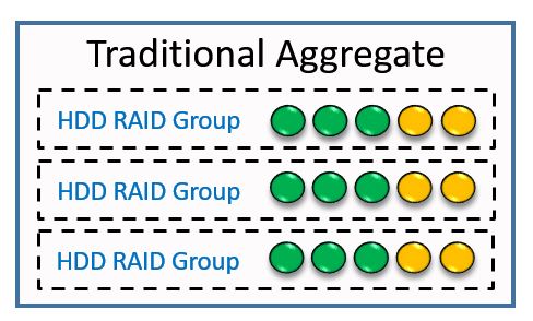
Traditional Aggregate
We can convert that to a Flash Pool aggregate by adding SSDs to it.
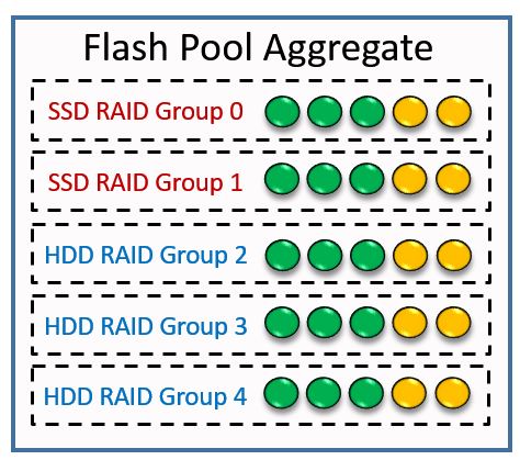
Flash Pool Aggregate
As well as converting existing aggregates to Flash Pool aggregates, we can also configure new aggregates for Flash Pool when we first create them.
The SSDs don’t increase the usable capacity of that aggregate. They are used purely as a cache to improve performance.
Caching for Random Reads
Random reads from the aggregate will be cached in the SSDs as this gives large performance gains. Sequential reads are not cached as the HDDs already provide comparatively good performance for these.
Flash Pool works very similarly to Flash Cache. Let’s look at an example.
We have green data in System Memory which was a random read from the Flash Pool aggregate.
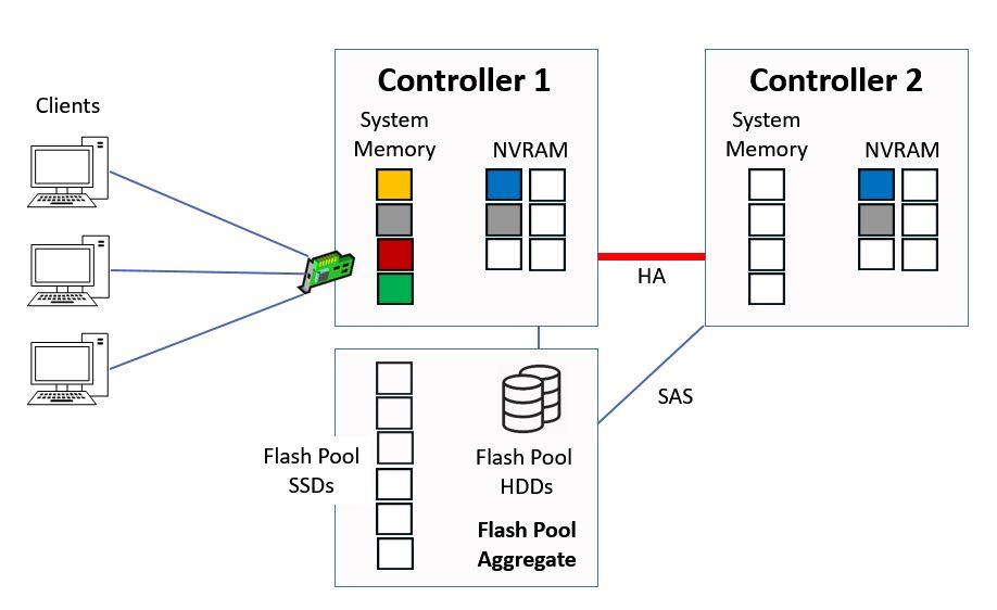
Flash Pool
When the next Consistency Point is taken, the data will be written to the SSD cache in the aggregate.
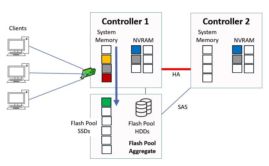
Flash Pool Cache
The block that is sent to the SSD cache is a copy of the block that already exists on the Flash Pool HDDs. It now exists on both HDD and SSD in the Flash Pool.
Caching for Random Overwrites
An advantage that Flash Pool has over Flash Cache is that SSDs are permanent storage, so we can cache writes as well as reads.
A random overwrite is defined as the same data block that is randomly written more than once. The first write is sent to HDD in our Flash Pool aggregate.
Random overwrites (which are performance intensive for HDD) will be sent to the SSD instead of to the HDD storage if their block size is 16kB or smaller. The earlier written block on HDD will be marked invalid.
Unlike cached reads which are on both HDD and SDD disks in the Flash Pool, the blocks that are cached as random overwrites are only on the aggregate’s SSD cache. They are not written to the aggregate’s HDD yet, but they will be moved there as they get aged out of the cache.
Sequential writes or random writes with a block size larger than 16kB will be sent to HDD as we get comparatively good performance for those on traditional spinning disks. We want to maximise the use of our SSD cache by storing data which will get the biggest benefit from being there.
The Flash Pool keeps track of all random read and write data that has been cached and determines which data is most used. As the cache becomes full and we need to make room for new data, the existing cached data that is less frequently used becomes eligible for ejection.
An eviction scanner is used for this process. We don’t need to remove old data while we still have space in the cache, so the scanner doesn’t run until the cache is 75% full.
Writes which are evicted from the cache are moved to HDD. Cached read blocks are already also on HDD, so no transfer is necessary for those.
You can think of how the eviction process works as taking steps up and down on a ladder. When data is written into the SSD cache, it has a value of ‘neutral’ and enters on the middle rung of the ladder.
The eviction scanner runs on a regular time interval. During each time period, if there has been a random read or overwrite for a piece of cached data, it will move up a rung on the ladder. If there hasn’t been a random read or overwrite for the data, it will move down a rung on the ladder.
When data drops off the bottom rung of the ladder it is evicted from the cache. This process ensures that our frequently accessed ‘hot’ data remains in the cache and gets the performance benefit.
Which Workloads are a Good Fit for Flash Pool?
Flash Pool is most effective at caching random reads and offloading those from the hard drives. It also provides benefit in offloading small random overwrites. An application workload that consists of mostly random reads or writes will benefit from Flash Pool.
Workloads that are mostly sequential will get limited benefit and are not recommended to be stored there.
Small working datasets that are likely to be served completely from System Memory are also not recommended.
The NetApp Automated Workload Analyzer can be run at the command line to determine Flash Pool candidacy for a workload and optimal cache size. Instructions are available on the NetApp website:
Determining Flash Pool Candidacy and Optimal Cache Size
Flash Cache and Flash Pool
With NetApp’s VST technologies of Flash Cache and Flash Pool, it’s not an either/or situation, you can use both in the same system.
When both Flash Cache and Flash Pool are enabled in the same system, we don’t waste space by double-caching. Data which is in Flash Pool aggregates can be cached on the Flash Pool SSDs, and other data can be cached in Flash Cache, but the same data is not eligible to be cached in both.
The System Memory cache is fastest and is always used first. Blocks can be moved to Flash Cache or Flash Pool as they’re aged out of System Memory.
Flash Cache vs Flash Pool Comparison
- FlashCache is plug and play
- It improves performance for random reads
- It improves performance for all aggregates on a controller
- If there is an unplanned HA takeover, the cache is lost
- Flash Pool aggregates are configured by the storage administrator
- It improves performance for random reads and random overwrites
- It improves performance for selected aggregates
- If there is an HA takeover, the cache is still present
HDD vs Flash Performance Comparison
The table below shows ballpark values for read latency when a NetApp FAS system is under up to fifty percent load for an average workload. The figures are for latency within the node and do not take the network latency between the client and storage system into account.
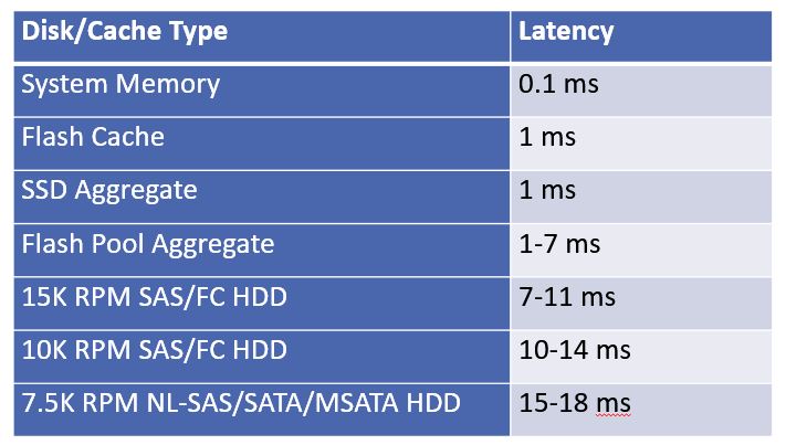
HDD vs Flash Performance
You can see the huge difference in performance between flash and spinning disk hard drive technologies. When you combine HDD hard drives, pure SSD aggregates, and cache in the same system, you can get a really good balance between performance and capacity at an acceptable price level.
Flash Pool Tutorial - NetApp VST Configuration Example
This configuration example is an excerpt from my ‘NetApp ONTAP 9 Complete’ course. Full configuration examples using both the CLI and System Manager GUI are available in the course.
Want to practice this configuration for free on your laptop? Download your free step-by-step guide ‘How to Build a NetApp ONTAP Lab for Free’
1. Enable Flash Pool on aggr1_C1N1. Use 4 SSD drives and RAID-4.
cluster1::> storage aggregate modify -aggregate aggr1_C1N1 -hybrid-enabled true
cluster1::> storage aggregate add-disks -aggregate aggr1_C1N1 -disktype ssd -diskcount 4 -raidtype raid4
Info: Disks would be added to aggregate "aggr1_C1N1" on node "cluster1-01" in the following manner:
First Plex
RAID Group rg1, 4 disks (block checksum, raid4)
Usable Physical
Position Disk Type Size Size
---------- ------------------------- ---------- -------- --------
parity NET-1.38 SSD - -
data NET-1.39 SSD 500MB 527.6MB
data NET-1.40 SSD 500MB 527.6MB
data NET-1.41 SSD 500MB 527.6MB
Aggregate capacity available for volume use would be increased by 1.32GB.
Do you want to continue? {y|n}: y
2. Verify Flash Pool has been enabled on the aggregate. What is the cache size?
cluster1::> storage aggregate show -aggregate aggr1_C1N1
Aggregate: aggr1_C1N1
Storage Type: hybrid
Checksum Style: block
Number Of Disks: 11
Mirror: false
Disks for First Plex: NET-1.2, NET-1.11,
NET-1.45, NET-1.3,
NET-1.12, NET-1.46,
NET-1.37, NET-1.38,
NET-1.39, NET-1.40,
NET-1.41
Disks for Mirrored Plex: -
Partitions for First Plex: -
Partitions for Mirrored Plex: -
Node: cluster1-01
Free Space Reallocation: off
HA Policy: sfo
Ignore Inconsistent: off
Space Reserved for Snapshot Copies: -
Aggregate Nearly Full Threshold Percent: 95%
Aggregate Full Threshold Percent: 98%
Checksum Verification: on
RAID Lost Write: on
Enable Thorough Scrub: off
Hybrid Enabled: true
Available Size: 3.51GB
Checksum Enabled: true
Checksum Status: active
Cluster: cluster1
Home Cluster ID: dbdbf221-22b4-11e9-996b-000c296f941d
DR Home ID: -
DR Home Name: -
Inofile Version: 4
Has Mroot Volume: false
Has Partner Node Mroot Volume: false
Home ID: 4082368507
Home Name: cluster1-01
Total Hybrid Cache Size: 1.46GB
Hybrid: true
Inconsistent: false
Is Aggregate Home: true
Max RAID Size: 24
Flash Pool SSD Tier Maximum RAID Group Size: 8
Owner ID: 4082368507
Owner Name: cluster1-01
Used Percentage: 0%
Plexes: /aggr1_C1N1/plex0
RAID Groups: /aggr1_C1N1/plex0/rg0 (block)
/aggr1_C1N1/plex0/rg1 (block)
RAID Lost Write State: on
RAID Status: mixed_raid_type, hybrid, normal
RAID Type: mixed_raid_type
SyncMirror Resync Snapshot Frequency in Minutes: 5
Is Root: false
Space Used by Metadata for Volume Efficiency: 0B
Size: 3.52GB
State: online
Maximum Write Alloc Blocks: 0
Used Size: 176KB
Press <space> to page down, <return> for next line, or 'q' to quit... q
3. How much did the available capacity increase on the aggregate?
The capacity is still 3.51GB. Flash Pool does not increase the available capacity of an aggregate.
4. Create a storage pool named StoragePool1 using 6 SSD disks. Use the ‘simulate’ option if using the CLI, note that creation will fail in System Manager when using the ONTAP simulator.
cluster1::> storage pool create -storage-pool StoragePool1 -disk-count 6 -simulate true
Info: Storage pool "StoragePool1" will be created as follows:
Disk Size Type Owner
---------------- ---------- ------- ---------------------
NET-1.42 520.5MB SSD cluster1-01
NET-1.43 520.5MB SSD cluster1-01
NET-1.44 520.5MB SSD cluster1-01
NET-1.29 520.5MB SSD cluster1-01
NET-1.30 520.5MB SSD cluster1-01
NET-1.31 520.5MB SSD cluster1-01
Allocation Unit Size: 702MB
This is the last part of the series. Part 1 of this series where I covered how reads and writes are handled by the system is available here: WAFL, NVRAM and the System Memory Cache
Join me for Part 2 here: Flash Cache – NetApp VST Virtual Storage Tier
Additional Resources
How NetApp AFF Improves Performance
NetApp - What is Flash Storage?
Click Here to get my 'NetApp ONTAP 9 Storage Complete' training course.