In this NetApp tutorial, you’ll learn about NIC teaming and how it works. Scroll down for the video and also the text tutorial.
NetApp NIC Teaming Video Tutorial

Thomas Goreham

This course has played a pivotal role in my success. Yesterday I was offered the opportunity to work as a Technical Support Engineer for NetApp. Passing my NCDA was what really helped my career take off.
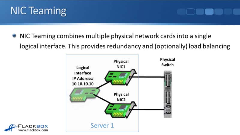
NIC teaming allows you to combine your physical NICs, which are your Network Interface Cards, into a single logical interface. This can be used to give you the benefits of load balancing and redundancy across multiple physical interfaces.
You can see in the diagram here, I’ve got my physical server, which has got two different physical network cards in there, and I grouped those into a single logical interface. This allows me to have a single IP address, which is 10.10.10.10 in our example here, being used across two different physical interfaces.
Another thing you could do is use two different IP addresses on your two different NICs. For example, 10.10.10.10 on the top NIC and 10.10.10.11 on the bottom one. Then you’ve got the same host being reached through two different IP addresses, and this makes your networking much more complicated.
It also makes it difficult to figure out how the redundancy and the failover are going to work for your host connecting in. It’s much easier if you can just use that one IP address on both those network cards, so you need to do NIC teaming to be able to do that.
NIC Teaming Names
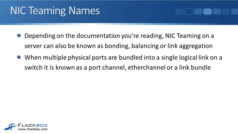
Depending on the documentation that you’re reading, there are many different names for NIC teaming. It can also be known as bonding, balancing, or link aggregation. Those are just different terms that all mean the same thing. So those are names when we’re talking about it on a server.
If we’re talking about bundling multiple physical ports on a switch into a single logical interface, we’ll call that either a port channel, etherchannel, or a link bundle. So, all of those terms basically mean the same thing.
Active/Standby Redundancy
I said earlier that the reason we do the NIC teaming is so that we can get redundancy, and optionally, load balancing. Our first option is we can do Active/Standby for the NIC teaming.
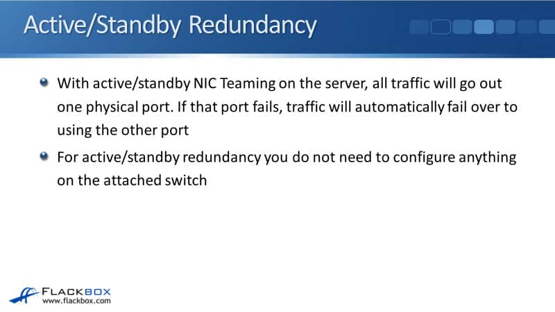
With Active/Standby, all traffic will go out one physical port. If that port fails, the traffic will automatically fail over to the other port, and for Active/Standby redundancy, you don’t need to configure anything on the attached switch.
Active/Standby gives us redundancy. One of the ports is always active. If it fails or if the actual cable it’s connected with fails, or if the switch port on the other side fails, then we’ll automatically fail over to the other physical port, still using the same IP address. So any client that is connecting to that host doesn’t need to change anything. It’s still connecting the one IP address.
The disadvantage of using Active/Standby, the good thing is it gives you the redundancy, but you don’t get any load balancing. Traffic is always going out only one interface at a time. So looking at the Active/Standby redundancy, you can see the same example again here.
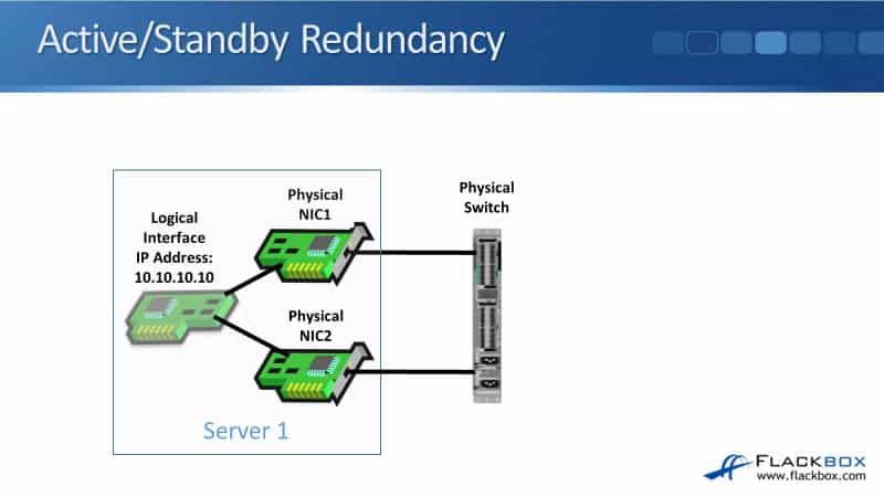
I’ve got my physical server with the two physical network cards in there. I give it that one IP address, 10.10.10.10, on that logical interface. In our example here, all traffic is going out of that top port. It’s only if the top port fails, it will failover to the bottom port. When that happens, the switch will learn that the MAC address for that server, has failed over to the bottom port.
So for this, you don’t need to configure anything different on the switch. You would just configure it with a normal access port for your VLAN on the switch.
Active/Active Redundancy and Load Balancing
With Active/Active NIC teaming, traffic will go out load balanced across all physical ports, and you get redundancy as well. If one of the ports fails, then all the traffic will go out of the remaining port. So with Active/Standby, you’re only using one port when you’ve got two physical ports there.
With Active/Active, you get to use both ports. So both are being actively used for traffic. You get the load balancing and the redundancy. So you’re probably thinking, “Well, why would I ever use Active/Standby? If I use Active/Active, I get the load balancing there.”
That gives you more bandwidth as well, right? Imagine, if those network ports are 10 gigabit Ethernet, if you’re using Active/Standby, you only ever get 10 gigabit Ethernet worth of bandwidth because you’re only using one port at a time.
If you’re using Active/Active, for that one server, when it’s sending out, it can actually get up to 20 gigabits of bandwidth because it’s using double the interfaces, it’s using both of them. So Active/Active looks a lot better, right? So why would we ever use Active/Standby?
Well, the reason is for active/active teaming, the server on the attached switch that it’s plugged into both needs to see the physical ports grouped into a single logical link.
So you need to configure the server, and you need to configure the switches plugged into with a matching configuration, so they both know that you’re using NIC teaming on that server. You don’t need to do that with Active/Standby.
With Active/Standby, the switch will learn automatically if it fails over from one port to the other. It will see the MAC address move from one port to the other, so you don’t need to do anything special on the switch.
But when you’re using the Active/Active load balancing, the switch sees that this is one thing on the other side, one MAC address, so it needs to know that that one MAC address is reachable through the two different ports. So we need to have a protocol that’s used for the matching configuration on the server and on the switch.
The protocol that is used for that negotiation is either Static 802.3ad or Link Aggregation Control Protocol (LACP). LACP is the newer protocol. It’s got some benefits over static, so it’s preferred to use LACP. You can only do that if both the server and the switch support LACP.
Active/Active Redundancy
You know how I was saying, why would you ever not use Active/Active? If a server supports Active/Active, but the switch doesn’t, then you can’t do that, but you could still use Active/Standby. Typically, modern switches will always support this.
Often, we will use Active/Active, and LACP has been around for quite a long time as well. So typically, we would use Active/Active LACP.
With Active/Active redundancy, it looks exactly the same. With the outside world again, we’ve got those two physical NICs. We’ve got that one IP address on there, 10.10.10.10 on the logical interface.
With the Active/Active redundancy, the server can send out both ports at the same time. So we get double the bandwidth. We get the load balancing. If anyone port fields, all the traffic will just go out of the remaining port.

Option 1 – Switch Does Not Support LAG
Let’s look at the different options that we can use for NIC teaming. Option one, if this switch does not support link aggregation. The switch does not support configuring port channels. Well, you know the answer already. To do Active/Active, we need to have a matching configuration on the switch. So if a switch is not capable of doing that, we could use Active/Standby.
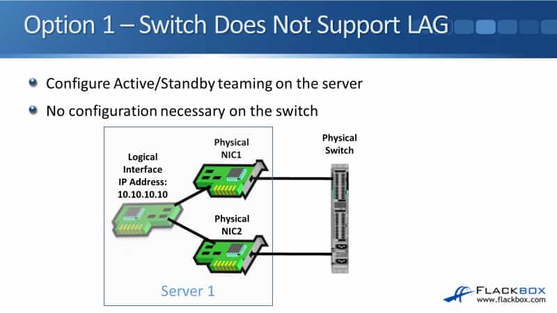
So, we do Active/Standby teaming on the server. When we configure the server, we go into the software there. We say we’re configuring NIC teaming, and we specify it’s going to be Active/Standby. On the switch that it’s plugged into, we just configure the switch ports.
Those are normal access ports, and we don’t need to configure anything else. If the server does fail on the link that is active, the switch will learn automatically to use the other link to get to that server.
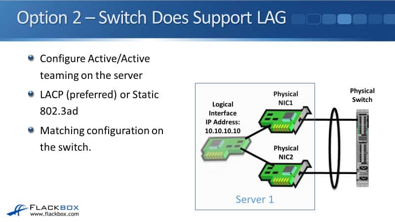
Option 2 – Switch Does Support LAG
Our next option, option two, the switch does support link aggregation. In that case, we can configure Active/Active teaming on the server, and we do a matching configuration on the switch as well. If both the server and the switch support it, it’s preferred to use LACP.
If either one of them is older and only supports static, then we’d use static on both sides. Whenever you see a network diagram where we do have link aggregation, a port channel configured on a switch, you’ll see it drawn like this, where we draw a ring, a circle, around the interfaces that are in that port channel.
Active/Active Redundancy and Load Balancing
With options one and two, you notice there was a single attached switch. Let’s go back a slide. So I’ve got two network cards so that I don’t have a single point of failure.
However, they’re both plugged into the same switch. So this switch is a single point of failure. It would be good if we could plug the two different NICs into two different switches. That is possible as well. That’s option three.
Option 3 – 2 Switches, No Dual Switch LAG Support
With option three, we’ve got two switches here, but there’s no dual switch link aggregation support. So most modern switches, even if they’re not expensive switches, will support link aggregation when the server has got two ports plugged into the same switch.
However, typically, you’re going to need a higher-end switch if you want to have two switches with the same shared port channel going down.
With those two switches that are connected to the one physical server on the different ports, that is a single port channel going down. So the two switches, the two separate physical switches, need to talk to each other and agree that they’ve got a shared port channel going down.
To be able to do that, you need a higher-end switch, which is not supported on most of your office shelf switches that you can buy.
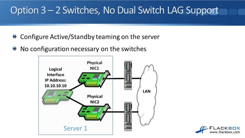
So if you do want to have two separate network cards and two separate switches, and the switches do not support that shared port channel going down, which is very common, then what we can do again is do Active/Standby teaming on the server. So you see in the diagram here, we’ve got NIC1 is connected to Switch1. NIC2 is connected to Switch2.
On the switches, we just configured them as normal VLAN access ports. It doesn’t know anything about there being in the NIC teaming on the server. On the server, we do configure NIC teaming there, but we configured it as Active/Standby. So all the traffic goes out either NIC1 or NIC2 unless it fails, in which case it fails over to the other one.
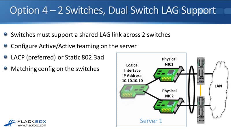
Option 4 – 2 Switches, Dual Switch LAG Support
Finally, we’ve got option four, where we do have high-end switches that are capable of doing a shared port channel going downstream. So here on the server, we can do our Active/Active teaming again. Again, typically we will use LACP there.
On the two switches, we do a port channel going downstream, which is also LACP and matches the configuration on the server. The two switches also need to talk to each other and agree that they’ve got that sheared port channel going down.
Okay, so that is all of the different options for our NIC teaming. Again, on the NetApp system, it counts as an end host, and we can do NIC teaming on the NetApp system as well.
Additional Resources
Troubleshooting LACP Port Channel/ Interface Groups: https://kb.netapp.com/Advice_and_Troubleshooting/Data_Storage_Systems/Fabric_Interconnect_and_Management_Switches/Troubleshooting_LACP_port_channel%2F%2F_interface_groups
Link Aggregation and IFGRP Troubleshooting: https://kb.netapp.com/Advice_and_Troubleshooting/Data_Storage_Software/ONTAP_OS/Link_aggregation_and_ifgrp_troubleshooting
NetApp Interface Groups Tutorial: https://www.flackbox.com/netapp-interface-groups-tutorial
Libby Teofilo

Text by Libby Teofilo, Technical Writer at www.flackbox.com
Libby’s passion for technology drives her to constantly learn and share her insights. When she’s not immersed in the tech world, she’s either lost in a good book with a cup of coffee or out exploring on her next adventure. Always curious, always inspired.