In this Cisco CCNA tutorial, you’ll learn why we have the Spanning Tree protocol. To understand why we need to have it, I need to first start off with a review of ethernet path selection. Scroll down for the video and also text tutorial.
Why We Have The Spanning Tree Protocol Video Tutorial
Lee Gaines
I have passed my CCNA with the help of your course, and landed a job as a network administrator at a local hospital for my first real IT job. I am so excited about getting started in this role. Thanks for all your help in helping me make huge strides in getting into this exciting new career path!
Ethernet Path Selection Review
We've got our example network topology on the left-hand side here again. Our Layer 2 ethernet path selection is controlled by the switch's MAC address tables.
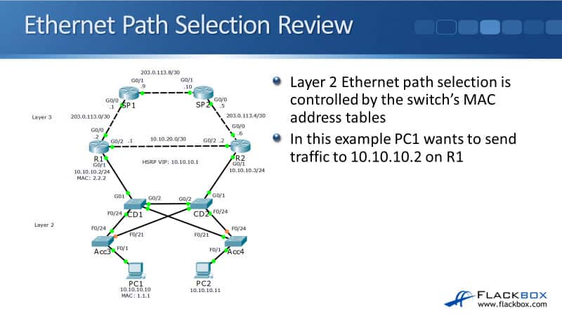
Let's see how those are built and how it works. In this example, PC1 wants to send traffic to the 10.10.10.2 IP address on R1. First, I'll cover what would happen if we didn't have Spanning Tree and then you'll understand why we need to have it.
PC1 hasn't spoken to R1 before, so it sends an ARP request for 10.10.10.2. That goes out with a source MAC of 1.1.1, The MAC address on PC1, and a destination MAC of F.F.F because it's broadcast traffic.

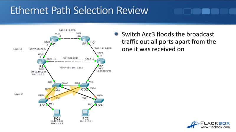
PC1 sends it out and it will hit switch Acc3. Acc3 learns that MAC address 1.1.1 is available via interface FastEthernet 0/1 because it saw that as the source MAC address in the incoming frame. Any subsequent traffic that is going to 1.1.1 that hits switch Acc3 will be forwarded out port FastEthernet 0/1 .

Switch Acc3 floods that broadcast ARP request out all ports apart from the one it was received on. It goes out interfaces FastEthernet 0/24 and FastEthernet 0/21.
Switch CD1 learns that MAC address 1.1.1 is available via interface FastEthernet 0/24 then that ARP request comes in. When it comes in, switch CD2, it learns that the MAC address 1.1.1 is available via its interface FastEthernet 0/21.
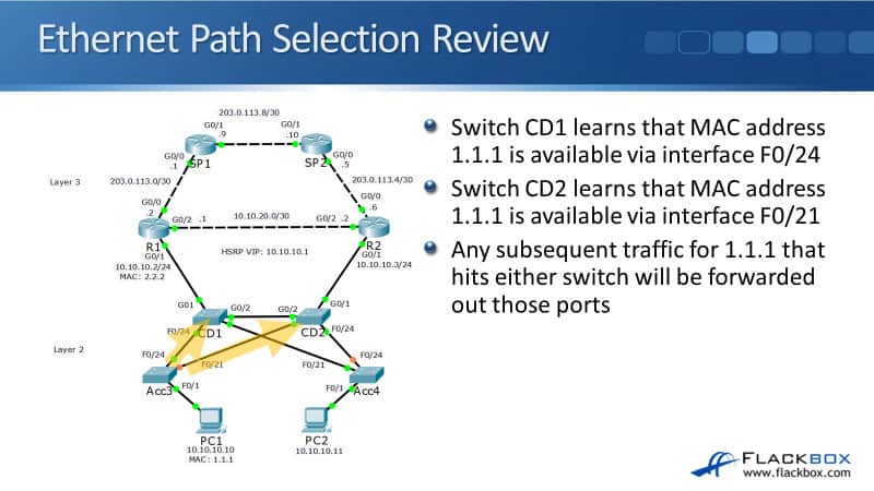
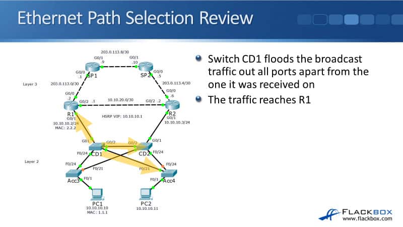
You can see that the MAC address tables are getting built on the switches here as traffic hits them. Any subsequent traffic for 1.1.1 that hits either CD1 or CD2 will be forwarded out those relevant ports. Switch CD1 floods the broadcast traffic at all parts apart from the one that it was received on there. The traffic will then reach R1, CD2, and Acc4.
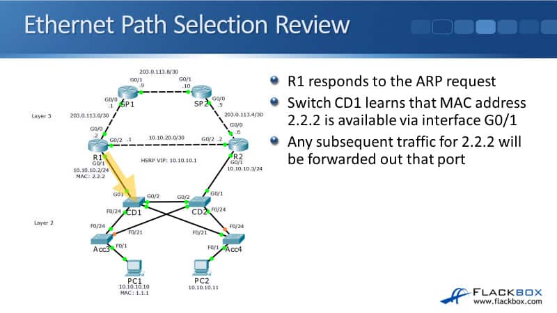
R1 will respond to the ARP request. CD1 learns that MAC address 2.2.2 on R1 is available via interface GigabitEthernet 0/1 from the ARP reply. Any subsequent traffic for 2.2.2 will be forwarded out of that port. Switch CD1 now knows the best ports to send traffic out for both R1 and PC1.
Switch CD1 already knows to forward the ARP request for 1.1.1 out towards PC1 on interface FastEthernet 0/24.
It comes into switch access three and it learns that MAC 2.2.2, the source address, and the ARP reply from R1 is available via interface FastEthernet 0/24. Any subsequent traffic for 2.2.2 that hit switch access three will be forwarded out port FastEthernet 0/24.
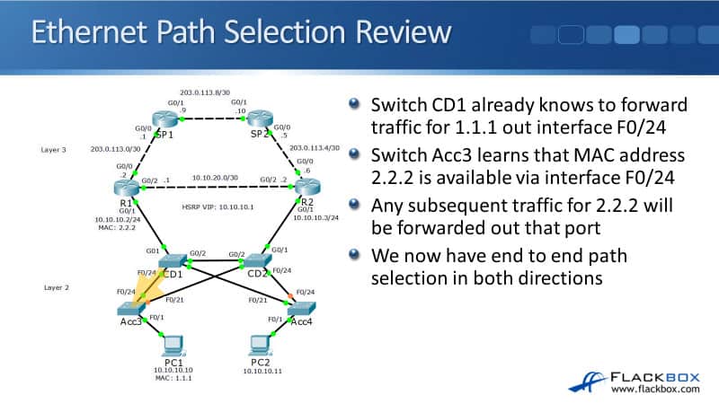
We now have an end to end path selection in both directions between PC1 and R1 going through the switches Acc3 and CD1. The switches knew which port to send the traffic out of. But, there's a problem here.
Layer 2 Loops
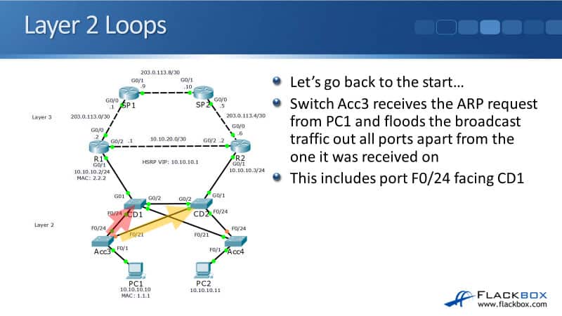
Switch Acc3 received the ARP request from PC1 and it floods the broadcast traffic out all ports apart from the one it was received on. This is if we don't have Spanning Tree. That includes port FastEthernet 0/24 facing CD1 and the port facing CD2, as well.
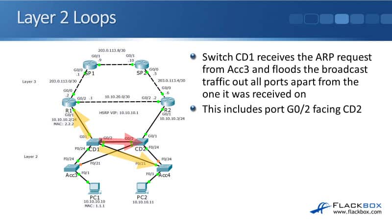
Switch CD1 receives the ARP request from access three and it floods the broadcast traffic out all ports apart from the one that was received on. That includes going out it's an interface GigabitEthernet 0/2 towards CD2 and CD2 does the same thing.
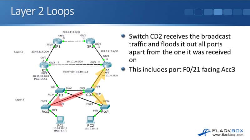
It floods the broadcast traffic out all ports apart from the one it was received on and that includes port FastEthernet 0/21 which is facing back towards switch Acc3, again.
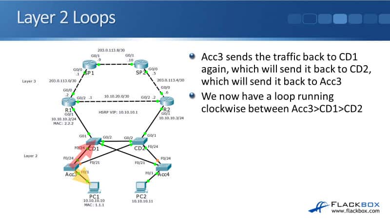
The traffic comes into Acc3, and Acc3 sends the traffic back to CD1 again, which will then send it back to CD2, which will then send it back to Acc3, and so on. We now have a loop running clockwise between the Acc3, CD1, and CD2 switches whenever we've got broadcast traffic. It's going to keep on looping between the three of them.
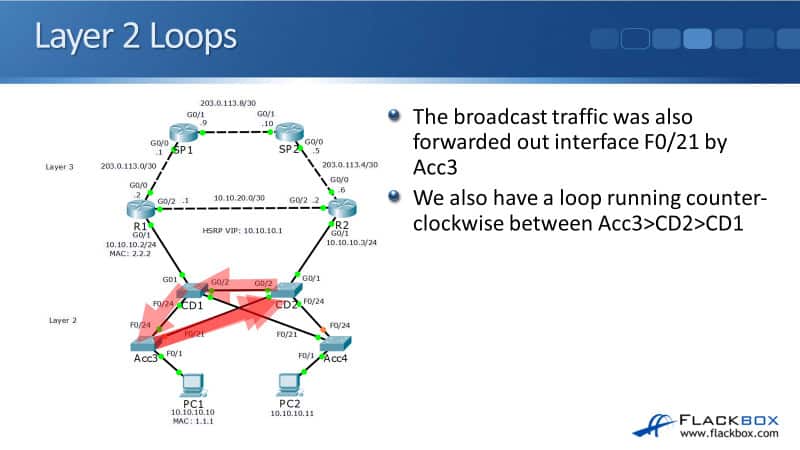
But, it doesn't end there. The broadcast traffic was also forwarded out interface FastEthernet 0/21 by Acc3 when the ARP request came in. So, we also have a loop running counterclockwise between Acc3, CD2, and CD1.
You can see the ARP request comes in, Acc3 sends it to CD2, CD2 sends it to CD1, CD1 to Acc3, Acc3 back to CD2, and so on. We have loops running in both directions, both clockwise and counterclockwise between Acc3, CD1, and CD2. Still, it doesn't stop there because the broadcast traffic was also forwarded out interface FastEthernet 0/21 by switch CD1.
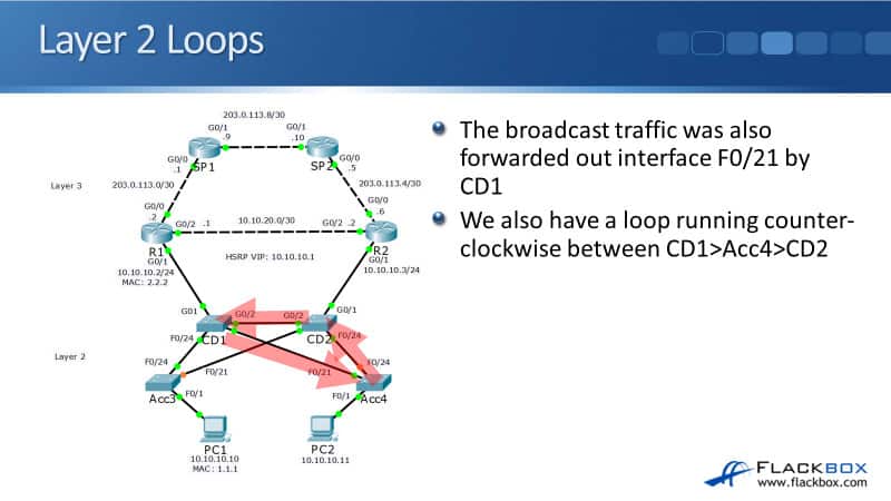
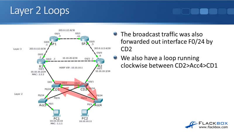
We also have a loop running counterclockwise between CD1, Acc4, and CD2. The broadcast traffic was also flooded out interface FastEthernet 0/24 by CD2, so we also have a loop running clockwise between CD2, Acc4, and CD1.
Just like we have two loops running clockwise and counterclockwise between Acc3, CD1, and CD2, we have the same thing, two loops running clockwise and counterclockwise between Acc4, CD1, and CD2. We've got 4 loops running through the network here.
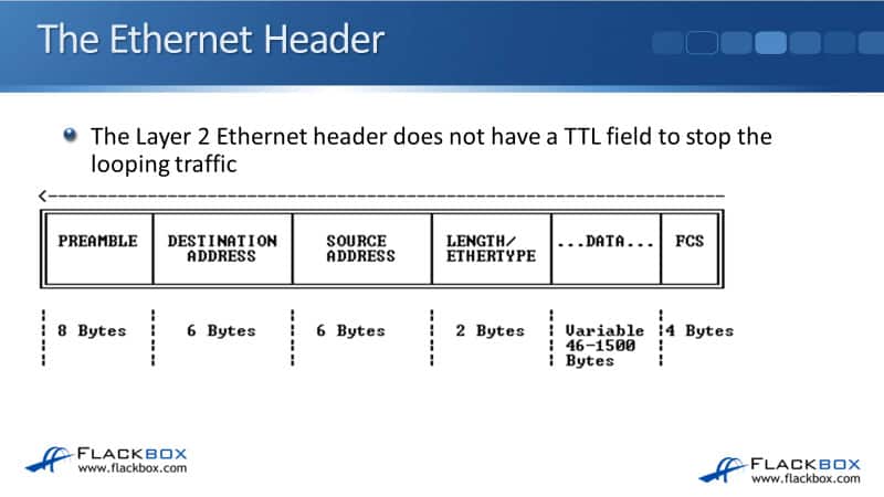
The Ethernet Header
The Layer 2 ethernet header does not have a TTL time to live field to stop the looping traffic like our Layer 3 IP header does. So, on a Layer 2 network, if you get traffic looping, it will loop forever.
There's nothing to stop that from happening. But, if you do get a loop happening, the way you can stop it is by physically going and unplugging a cable.
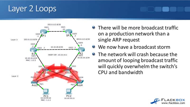
There's going to be more broadcast traffic on our network than just that single ARP request from PC1 going to R1. There's going to be loads of other broadcast traffic as well, like other ARP requests, DHCP requests, etc.
If we do have loops on the network with all that broadcast traffic going around, we're going to get a broadcast storm. The network will crash because the amount of looping broadcast traffic will quickly overwhelm the switches, CPU, and bandwidth.
STP Spanning Tree Protocol
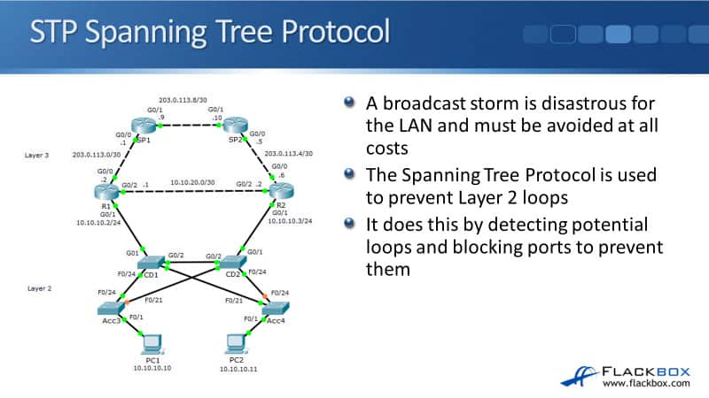
If you do get a broadcast storm on your network, it's devastating for the network. It will stop the network from working. A broadcast storm obviously must be avoided at all costs. The way that we do avoid it is by using the Spanning Tree protocol.
It's used to prevent any Layer 2 loops. It does that by detecting any potential loops and blocking ports to prevent them.
In our example network, you can see on the diagram on the left that there's a couple of links highlighted in red rather than in green. Port FastEthernet 0/21 on switch Acc3 is highlighted in red.
This means that it is being blocked to prevent the loops, both clockwise and counterclockwise that we're running between CD1, CD2, and Acc3.
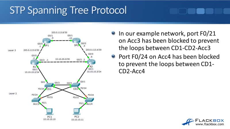
We also had that other loop between Acc4, CD1, and CD2 as well. On that side, port FastEthernet 0/24 on the Acc4 switch has been blocked. The spanning tree will detect potential loops and or block a port to break the loop.
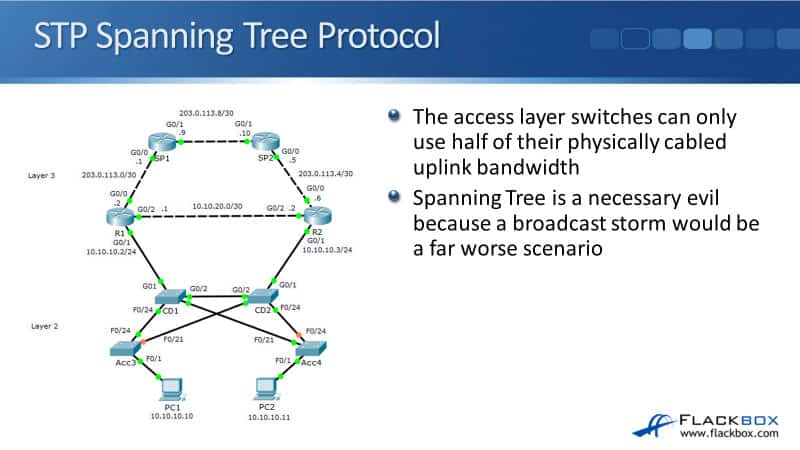
Without STP, from Acc3, if both uplinks FastEthernet 0/24 and FastEthernet 0/21 were up, we would be able to send traffic upstream to both CD1 and CD2 through the FastEthernet 0/24 and FastEthernet 0/21 interfaces.
Let's say that those are 1 Gb interfaces. We would have hired 2 Gb worth of uplink bandwidth. But, because one of those ports is being shut down, we're only using half of our available physically connected uplink bandwidth.
We've only got 1 Gb worth of uplink connectivity rather than 2 Gb. Spanning tree actually shuts down physically cabled interfaces. It reduces the amount of bandwidth that you have available. It's a necessary evil because if we've got a broadcast storm, the network wouldn't work at all, that would obviously be a far worst scenario.
Spanning Tree automates failover as well as performs loop prevention. In the example below, on both Acc3 and Acc4, the available uplink is the one facing towards CD1.
In the core distribution layer two switch, CD2, both the uplinks from our access to our switches to it are blocking to prevent the loops. But, if the switch CD1 goes down or the links to CD1 go down, Spanning Tree will detect that and it will fail the uplinks over to using CD2 instead.
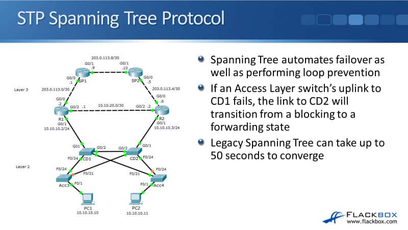
We already covered one of the bad things about Spanning Tree. It limits the amount of bandwidth you have by shutting down interfaces that are actually physically cabled. Another bad thing about Spanning Tree is, it typically has a slow convergence time. It can actually take up to 50 seconds to converge.
Spanning Tree got some bad things about it, but, it's absolutely necessary in networks. It's far more important to ensure that we don't have any Layer 2 loops. However, we would like to minimise the use of Spanning Tree, if we can.
Additional Resources
Understanding and Configuring Spanning Tree Protocol (STP) on Catalyst Switches: https://www.cisco.com/c/en/us/support/docs/lan-switching/spanning-tree-protocol/5234-5.html
Why Spanning Tree Is Important: A Demo: https://www.networkcomputing.com/data-centers/why-spanning-tree-important-demo
The Advantages of Spanning Tree Protocol: https://www.techwalla.com/articles/the-advantages-of-spanning-tree-protocol
Libby Teofilo

Text by Libby Teofilo, Technical Writer at www.flackbox.com
Libby’s passion for technology drives her to constantly learn and share her insights. When she’s not immersed in the tech world, she’s either lost in a good book with a cup of coffee or out exploring on her next adventure. Always curious, always inspired.