
In this Cisco CCNA tutorial, you’ll learn about Layer 3 EtherChannel. Scroll down for the video and also text tutorial.
Cisco Layer 3 EtherChannel Video Tutorial
Serhii Butko

Thank you very much for your course. I have passed the exam. My score is 948!
You can see that with the configuration example here that the configuration is actually exactly the same with Layer 2 EtherChannel. The only difference is that we make the port a Layer 3 port with the ‘no switchport’ command.
That's a standard command you can use on a Layer 3 switch, whether you're using EtherChannel or not. You can put an IP address on a Layer 3 port.
Now, let's look at the configuration. At global config, I've entered the commands:
interface range GigabitEthernet 1/0/1 – 2
no switchport
This will make to make the range of interfaces as Layer 3 ports, and then I'm going to configure them as a port channel using the command:
channel-group 1 mode | active | auto | desirable | on | passive
The options depend on whether you want to make it a static EtherChannel with on, or we can use active or passive for LACP, or we can use auto or desirable for PAGP.

We'll group the ports together into an EtherChannel, then, we can put our other configuration on that EtherChannel. That's where we're going to put our IP address. We say:
interface port-channel 1
The 1 ties up with the channel group number. In this example, we’ll configure the IP address as:
ip address 192.168.0.1 255.255.255.252
no shutdown
Layer 3 Campus Design
There’s something else I want to talk to you about here and that is the network design. Looking at our traditional campus design with the Core, Distribution, and Access layer, Layer 2 links between the Access Layer switches and the Distribution Layer switches.
The default gateway for the end hosts would be on the Distribution Layer switches, and we would have spanning tree running between the Access and the Distribution Layer because they're Layer 2 links.
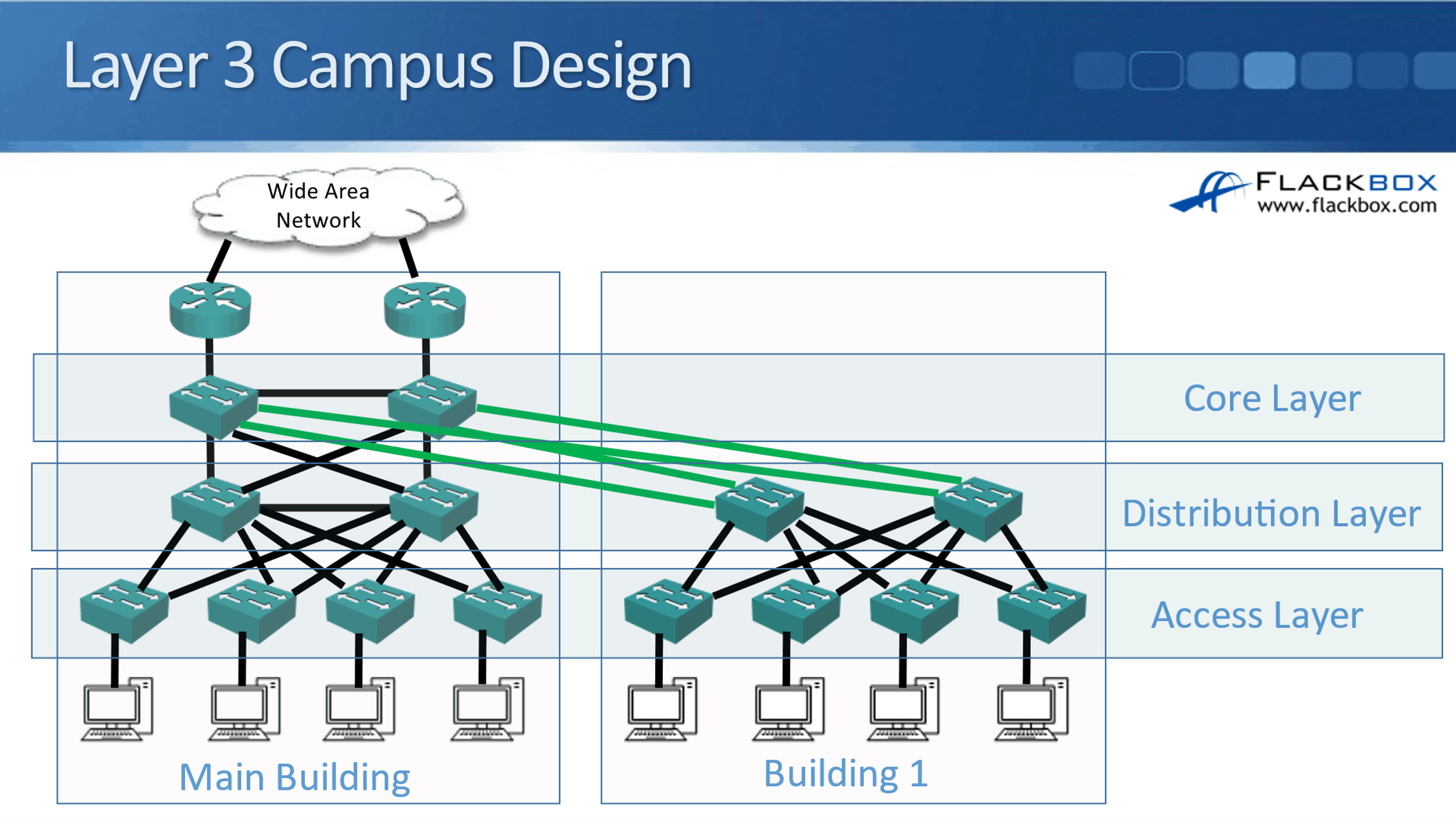
A trend that you can see increasingly now is actually putting Layer 3 links everywhere. The benefit you get from doing that is it means that you're not using spanning tree anymore. Spanning tree is a necessary evil.
The bad side of spanning tree is that it tends to shut down half of your links, and it's very slow to recover from failure as well. So it's bad, but it still does good things. You still need it, because it would be way worse if you had a Layer 2 loop in your network. That would just basically bring your network down.
We make sure that we don't have Layer 2 loops by having spanning tree enabled, but the bad side is that it's slow to recover from failures and it does shut down half our links. It would be better if we could have Layer 3 links everywhere, and not use spanning tree any more, right?
Now you may be wondering, well okay, well why didn't we always do that? Why did we use to have Layer 2 links between the Access Layer and the Distribution Layer? Now, in a lot of modern networks, we still do have Layer 2 links from the Access to the Distribution Layer, but an increasing trend that you'll see now is that Layer 3 everywhere.
The reason it's possible is that Layer 3 switches have come down in price a lot. Back in the day, Layer 3 switches were a lot more expensive than Layer 2 switches. Your Access Layer switches were where you had the high port count and where you had all of your hosts plugged in.
So, you had a lot of Access Layer switches and it just wasn't possible from a cost point of view to put Layer 3 switches in on all your Access Layer switches. But because time has moved on now and the prices have come down for Layer 3 switches, it is more feasible to do that now.
If you do put in Layer 3 switches everywhere, including in the Access Layer, you actually have the Layer 3 links from the Access Layer to the Distribution Layer. Meaning, you've got an IP address on the Access and Distribution switch ports. Because everything is Layer 3, you don't have spanning tree running anymore since spanning tree only works on Layer 2 links.
The way that you do have the paths being determined between your switches is by your routing protocol and not by spanning tree. When you're using Layer 3 links everywhere, you will configure a routing protocol as well, and it's up to the routing protocol to handle the path determination.
With your routing protocols, they support equal-cost load balancing. Therefore, you're not going to have links being shut down. All your links will still be available, and traffic will be load-balanced across all of them. Also, your routing protocols recover from failures. They converge a lot faster than spanning tree does. That's the benefit you get there.
Now when you do this, the default gateway is not going to be on the Distribution Layer switches. The default gateway for your end hosts is going to be on the Access Layer switches. If you think about it, we're going to have an IP subnet on the Access Layer – end host link, and we're going to have a different IP subnet on the Access – Distribution Layer link.
The default gateway for your hosts has to be in the same IP subnet. So, your default gateway is now going to be configured on your Access Layer switches, and you're going to have routing everywhere.
Cisco Layer 3 EtherChannel Configuration Example
This configuration example is taken from my free ‘Cisco CCNA Lab Guide’ which includes over 350 pages of lab exercises and full instructions to set up the lab for free on your laptop.
Click here to download your free Cisco CCNA Lab Guide.

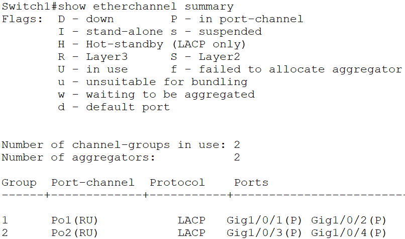
- Switch1 and Switch2 are connected together with their GigabitEthernet1/0/1 and 1/0/2 interfaces.
Configure these interfaces as a Layer 3 Etherchannel with LACP.
Configure IP address 192.168.0.1/30 on Switch1 and 192.168.0.2/30 on Switch2.
You can use your choice of number for the channel-group. Starting at ‘1’ and using the same number on both sides keeps the configuration logical and easier to troubleshoot.
Switch1(config)#interface range GigabitEthernet 1/0/1 - 2
Switch1(config-if-range)#no switchport
Switch1(config-if-range)#channel-group 1 mode active
Switch1(config-if-range)#exit
Switch1(config)#interface port-channel 1
Switch1(config-if)#ip address 192.168.0.1 255.255.255.252
Switch1(config-if)#no shutdown
Switch2(config)#interface range GigabitEthernet 1/0/1 - 2
Switch2(config-if-range)#no switchport
Switch2(config-if-range)#channel-group 1 mode active
Switch2(config-if-range)#exit
Switch2(config)#interface port-channel 1
Switch2(config-if)#ip address 192.168.0.2 255.255.255.252
Switch2(config-if)#no shutdown
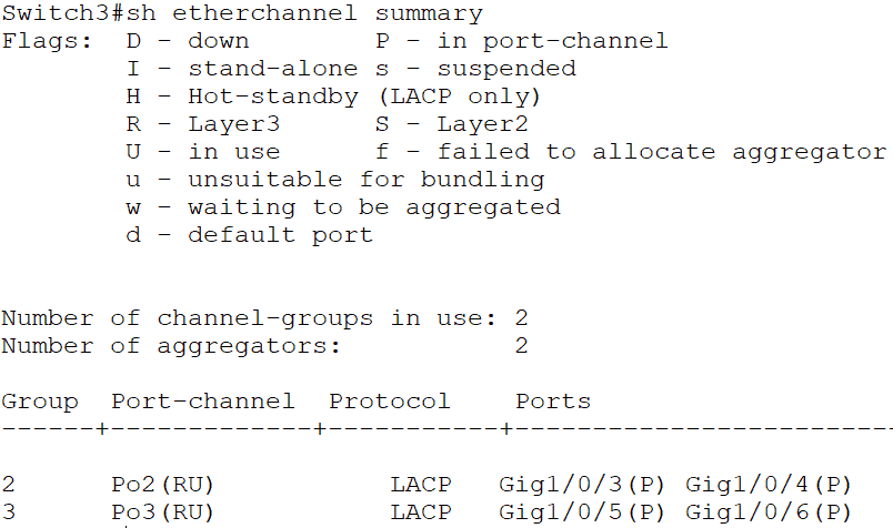
2. Switch1 and Switch3 are connected together with their GigabitEthernet1/0/3 and 1/0/4 interfaces.
Configure these interfaces as a Layer 3 Etherchannel with LACP.
Configure IP address 192.168.0.5/30 on Switch1 and 192.168.0.6/30 on Switch3.
Switch1(config)#interface range GigabitEthernet 1/0/3 - 4
Switch1(config-if-range)#no switchport
Switch1(config-if-range)#channel-group 2 mode active
Switch1(config-if-range)#exit
Switch1(config)#interface port-channel 2
Switch1(config-if)#ip address 192.168.0.5 255.255.255.252
Switch1(config-if)#no shutdown
Switch3(config)#interface range GigabitEthernet 1/0/3 - 4
Switch3(config-if-range)#no switchport
Switch3(config-if-range)#channel-group 2 mode active
Switch3(config-if-range)#exit
Switch3(config)#interface port-channel 2
Switch3(config-if)#ip address 192.168.0.6 255.255.255.252
Switch3(config-if)#no shutdown
3. Switch2 and Switch3 are connected together with their GigabitEthernet1/0/5 and 1/0/6 interfaces.
Configure these interfaces as a Layer 3 Etherchannel with LACP.
Configure IP address 192.168.0.9/30 on Switch2 and 192.168.0.10/30 on Switch3.
Switch2(config)#interface range GigabitEthernet 1/0/5 - 6
Switch2(config-if-range)#no switchport
Switch2(config-if-range)#channel-group 3 mode active
Switch2(config-if-range)#exit
Switch2(config)#interface port-channel 3
Switch2(config-if)#ip address 192.168.0.9 255.255.255.252
Switch2(config-if)#no shutdown
Switch3(config)#interface range GigabitEthernet 1/0/5 - 6
Switch3(config-if-range)#no switchport
Switch3(config-if-range)#channel-group 3 mode active
Switch3(config-if-range)#exit
Switch3(config)#interface port-channel 3
Switch3(config-if)#ip address 192.168.0.10 255.255.255.252
Switch3(config-if)#no shutdown
4. Verify the EtherChannels come up.

5. Configure Switch1, Switch2 and Switch3 to advertise the IP subnets configured on their Etherchannel interfaces in OSPF Area 0.
On Switch1, Switch2 and Switch3:
Switch1(config)#ip routing
Switch1(config)#router ospf 1
Switch1(config-router)#network 192.168.0.0 0.0.0.255 area 0
6. Verify the OSPF adjacencies are formed successfully.
On Switch1, Switch2 and Switch3:

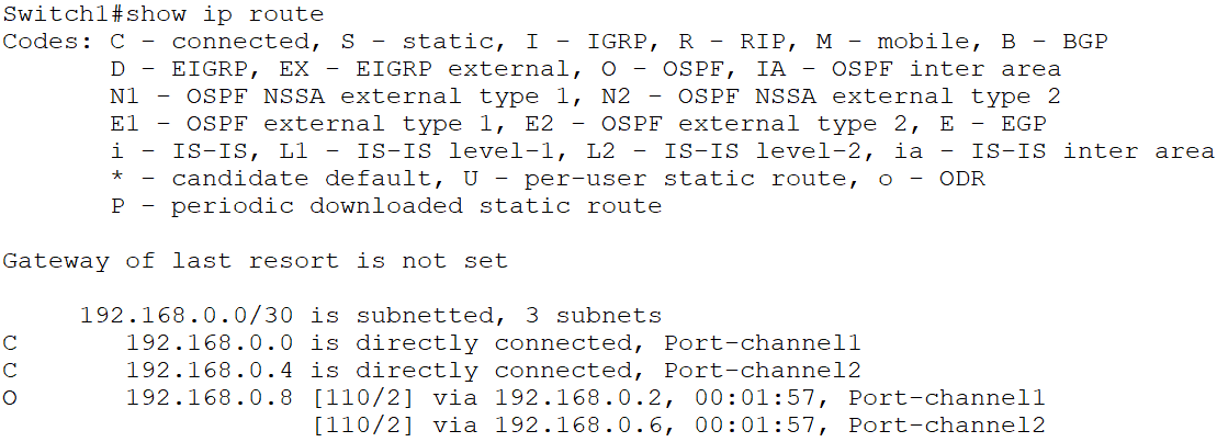
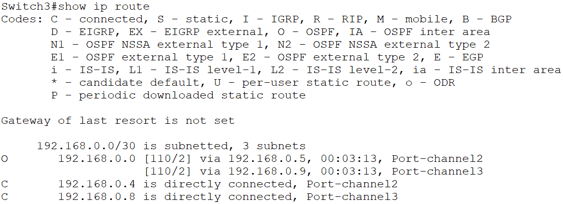
7. Verify Switch1, Switch2 and Switch3 have routes to all configured networks in their routing tables.

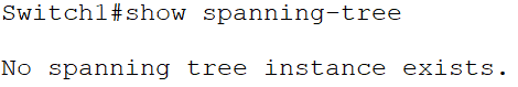
8. Which physical ports on which switches do you expect the Spanning Tree protocol to disable? Verify this.
Spanning Tree only runs on Layer 2 interfaces. It will not run on or shut any of the ports down as they are all Layer 3 ports. The Layer 3 switches’ routing tables will handle path selection, redundancy and load balancing.
Additional Resources
Layer 3 Etherchannel on Cisco IOS Switch: https://networklessons.com/switching/layer-3-etherchannel-cisco-ios-switch
Layer 2 and Layer 3 Configuration Guide: https://www.cisco.com/c/en/us/td/docs/switches/lan/catalyst9500/software/release/16-6/configuration_guide/b_166_lyr2_lyr3_9500_cg/b_166_lyr2_lyr3_9500_cg_chapter_011.html
Libby Teofilo

Text by Libby Teofilo, Technical Writer at www.flackbox.com
Libby’s passion for technology drives her to constantly learn and share her insights. When she’s not immersed in the tech world, she’s either lost in a good book with a cup of coffee or out exploring on her next adventure. Always curious, always inspired.