In this Cisco CCNA tutorial, you’ll learn about why we have EtherChannel. Scroll down for the video and also text tutorial.
Why We Have EtherChannel Video Tutorial
Armand Picari

I watched your course and I passed my CCNA. Now I am working for the network team in my company. Thank you for the great videos!
Campus Design – Oversubscription
We'll start off by having a very quick review of the campus design model. Our end hosts, like our PCs, get plugged into our access layer switches. Our access layer switches uplink to the distribution layer switches, and then they uplink to the core layer switches.
End hosts do not constantly send traffic onto the network, most of the time their network connection is sitting idle. If you think about what you're doing, when you're sitting on a PC, if you're working on a Word document or an Excel spreadsheet or something like that, there's no traffic actually going over the network.
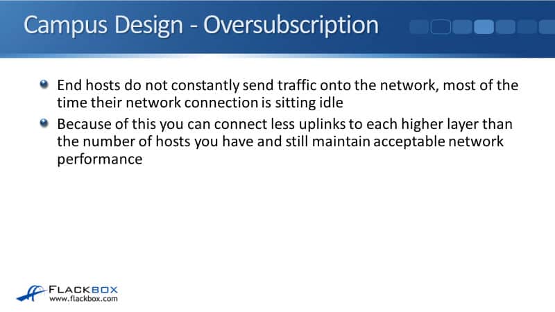
Because of this, you can connect on less uplinks to each higher layer than the number of hosts you have and still maintain acceptable network performance. You don't need to support all of the possible bandwidth that your hosts have, because we're not all going to be using it at the same time.
In our example, we've got our two buildings, we've got four access layer switches in each building for the example, and let's say that they are 48 port switches, and I've got 40 end hosts plugged into each switch.
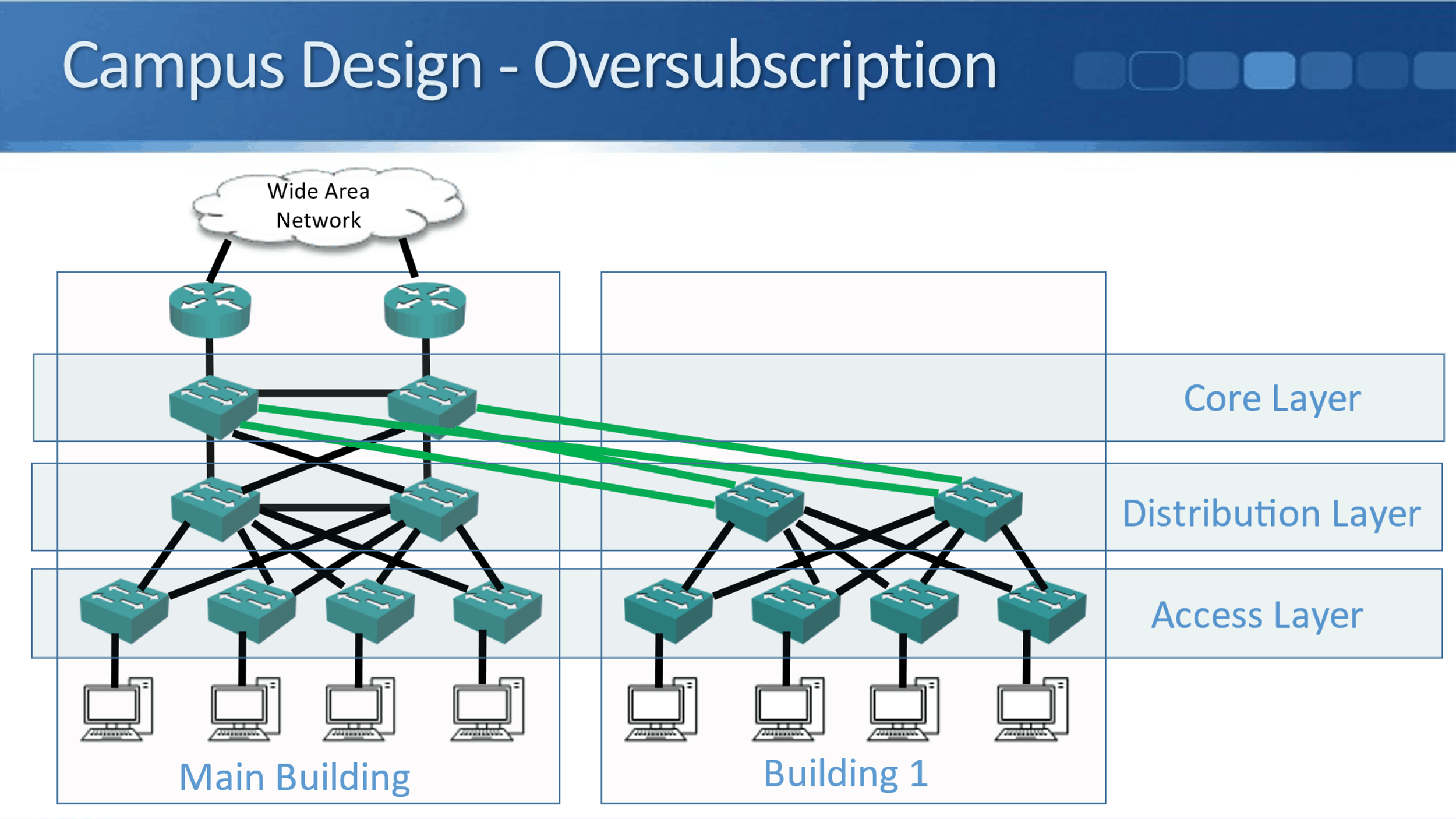
That would be 4 times 40, 160 hosts in the Main Building and 160 hosts in Building 1 as well. They're uplinking to a pair of distribution switches in both buildings. So I've got 160 devices in both buildings, but I don't have 160 uplinks going from the access layer to the distribution layer.
Also, I don't have that amount of uplinks going from the distribution layer up to the core layer. I don't need to put that many in because I know that my PCs are not going to be transmitting at the same time, they don't actually need that much bandwidth.
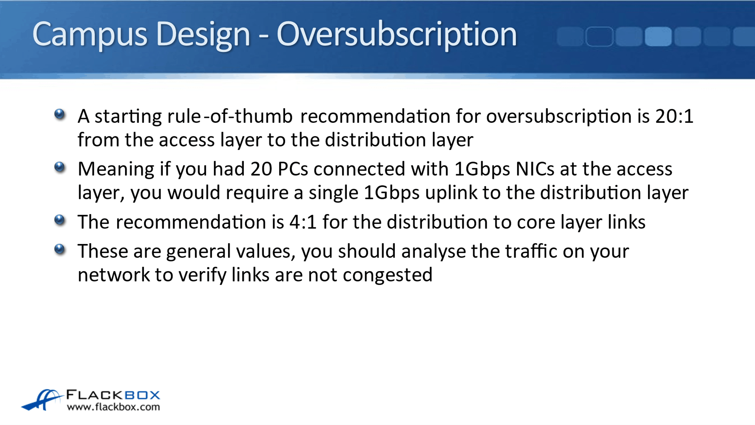
A starting rule of thumb recommendation for how much oversubscription you should have in your campus line is 20 to one from the access layer to the distribution layer. Meaning, if you had 20 PCs connected with 1 Gbps network cards at the access layer, you would require a single 1 Gbps uplink to the distribution layer to support their traffic.
The recommendation is 4:1 for the distribution to core layer links. Bear in mind that those are general values, you should analyze the traffic on your network to verify that your links are not congested. It depends on particular traffic patterns on your network, what applications you're running, etc., what will be a good oversubscription ratio for you, but these are good ballpark figures.
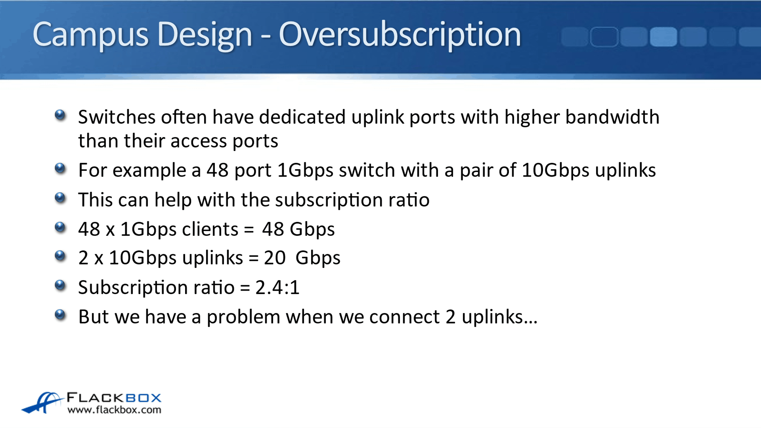
Switches often have dedicated uplink ports, which have got higher bandwidth than the bandwidth on their access ports. For example, a 48 port 1 Gbps switch with a pair of 10 Gbps uplinks. That can help with the subscription ratio. If you've got 48 1 Gbps clients plugged into that switch, then the total bandwidth there possible would be 48 Gbps.
You've got your two 10 Gbps uplinks, so that's 20 Gbps on your uplink links. That gives a subscription ratio of 2.4 to 1. If we didn't have those 10 Gbps uplinks, if the uplinks were also 1 Gbps as well, the subscription ratio would be 24 to 1, which is obviously not as good.
Spanning Tree Load Balancing
Normally when you do have switches that have got higher bandwidth uplinks, then oversubscription is not going to be a problem. However, we do have a problem when we want to connect to uplinks, and that problem is Spanning Tree.
Spanning Tree provides redundancy, but it does not provide load balancing. Spanning Tree always selects one best path to avoid loops. If a switch has got multiple equal cost paths, they have the same neighbor switch towards the Root Bridge. It will then select one of those ports and it will go through the one which has got the lowest port ID. It's not going to load balance across all of them.
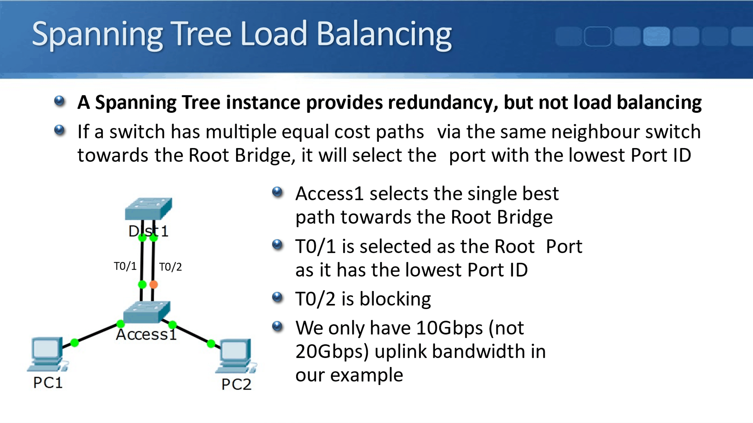
In our example above, we've got uplinks from our access layer, Access1 switch, going to the Dist1 switch. We've got 2 10 Gbps ethernet interfaces, 0/1, and 0/2, 0/1 will be selected as the root port as it has got the lowest port ID, and T0/2 is blocking.
Even though we physically connected to 10 Gbps ethernet uplinks, we only get 10 Gbps worth of link bandwidth, not the 20 Gbps because Spanning Tree is going to block one of those links.
EtherChannel
So that's the problem, we don't get all of our available physically connected uplink bandwidth. The solution is EtherChannel. EtherChannel-groups multiple physical interfaces into a single logical interface, and Spanning Tree then sees that EtherChannel as a single interface so it doesn't block any ports.
We now get the full 20 Gbps worth of bandwidth. Without EtherChannel, Spanning Tree sees that as a possible loop because traffic could go up T0/1 and then back down T0/2 and then back up T0/1 again.
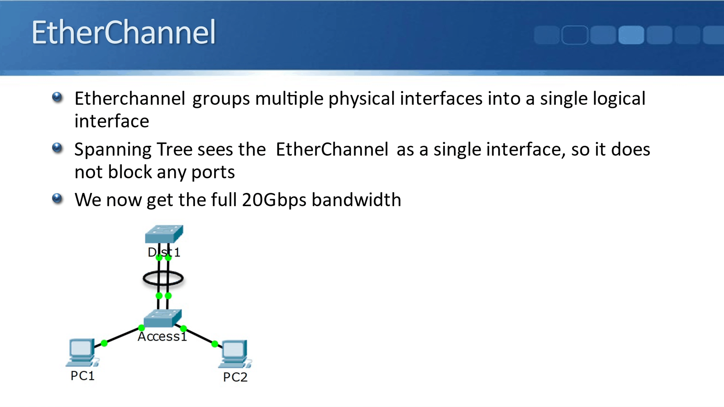
When we do configure EtherChannel for Spanning Tree, it counts as a single link and as a single interface on both sides. Spanning Tree does not see it as a potential loop, and now we get the full 20 Gbps worth of bandwidth.
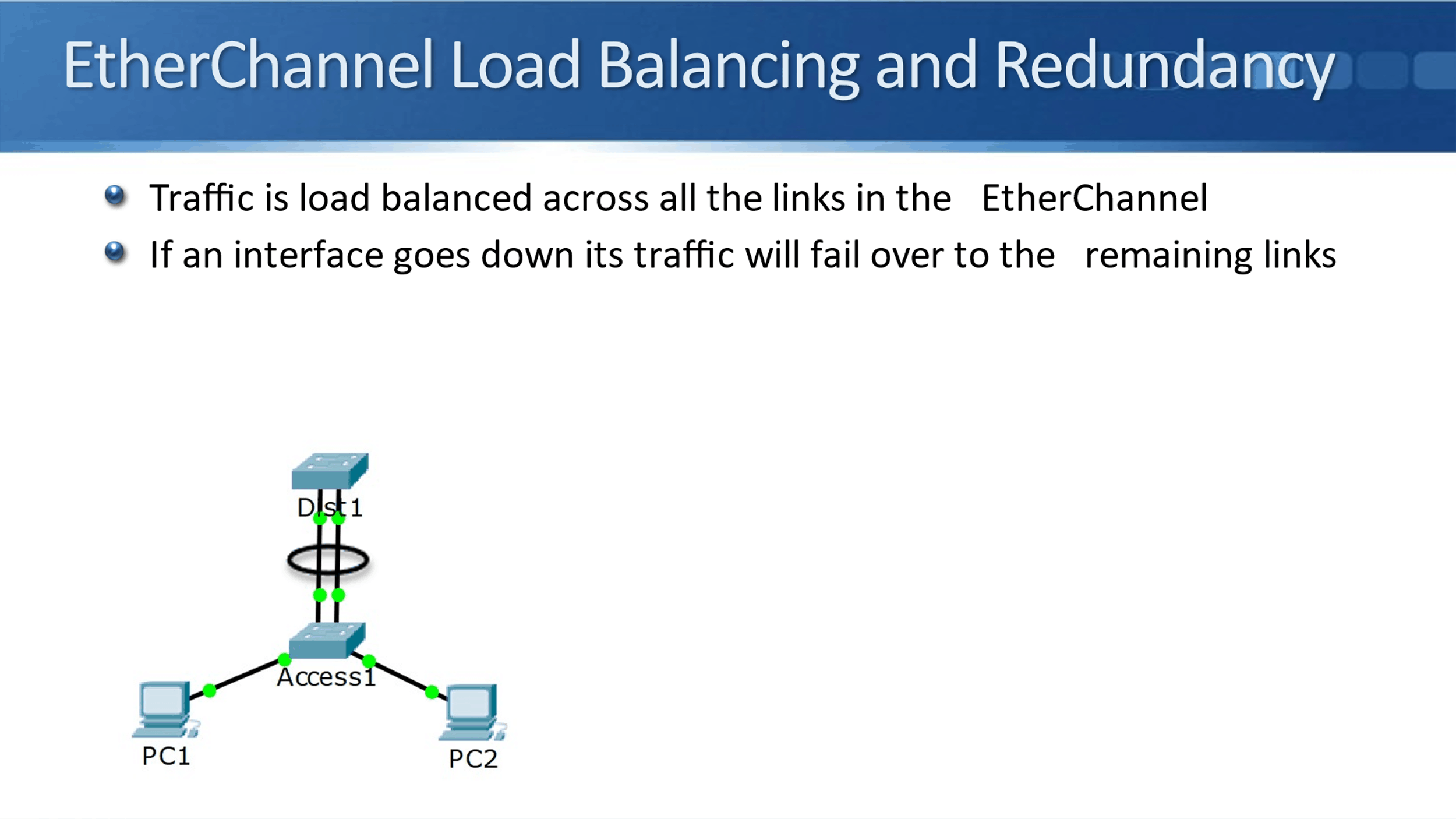
EtherChannel Load Balancing and Redundancy
Traffic will be load balanced across all the links that are in the EtherChannel. Therefore, the traffic from my PC is going upstream and is going to be load balanced across all the links. The same for the traffic coming back down in the other direction.
It doesn't just provide load balancing, it provides redundancy as well. If an interface goes down, its traffic will failover to the remaining links.
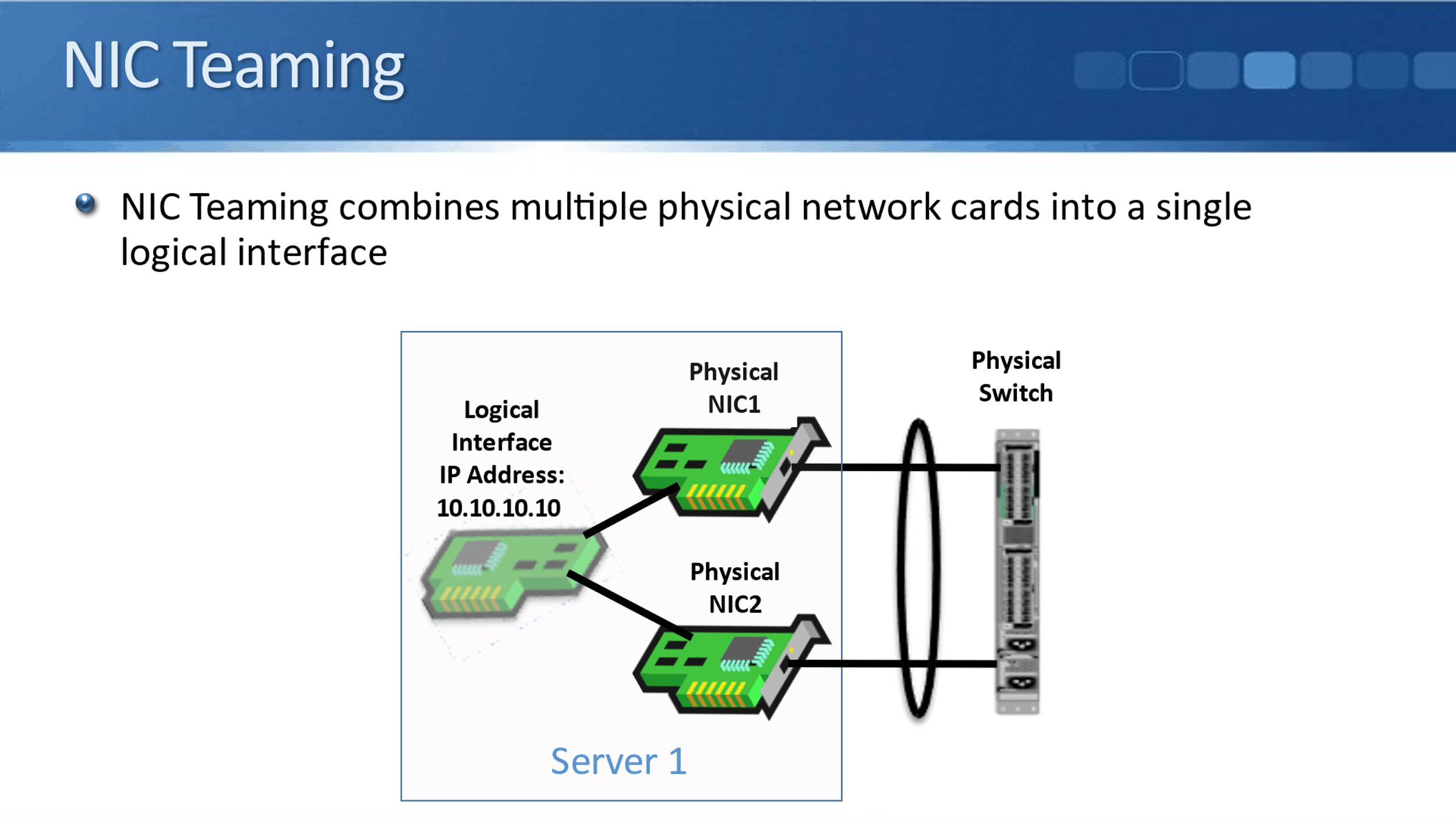
NIC Teaming
We can do basically the same thing on our servers as well with NIC Teaming. With EtherChannel, we can bundle multiple physical ports into a single logical port on our inter-switch links. On our servers, with NIC teaming we can bundle multiple physical network cards into a single logical interface.
The benefit we get from this is we get the load balancing and the redundancy again. Because the operating system sees it as a single interface, we just have one IP address on there, which makes things much more convenient and simple to configure.
Terminology
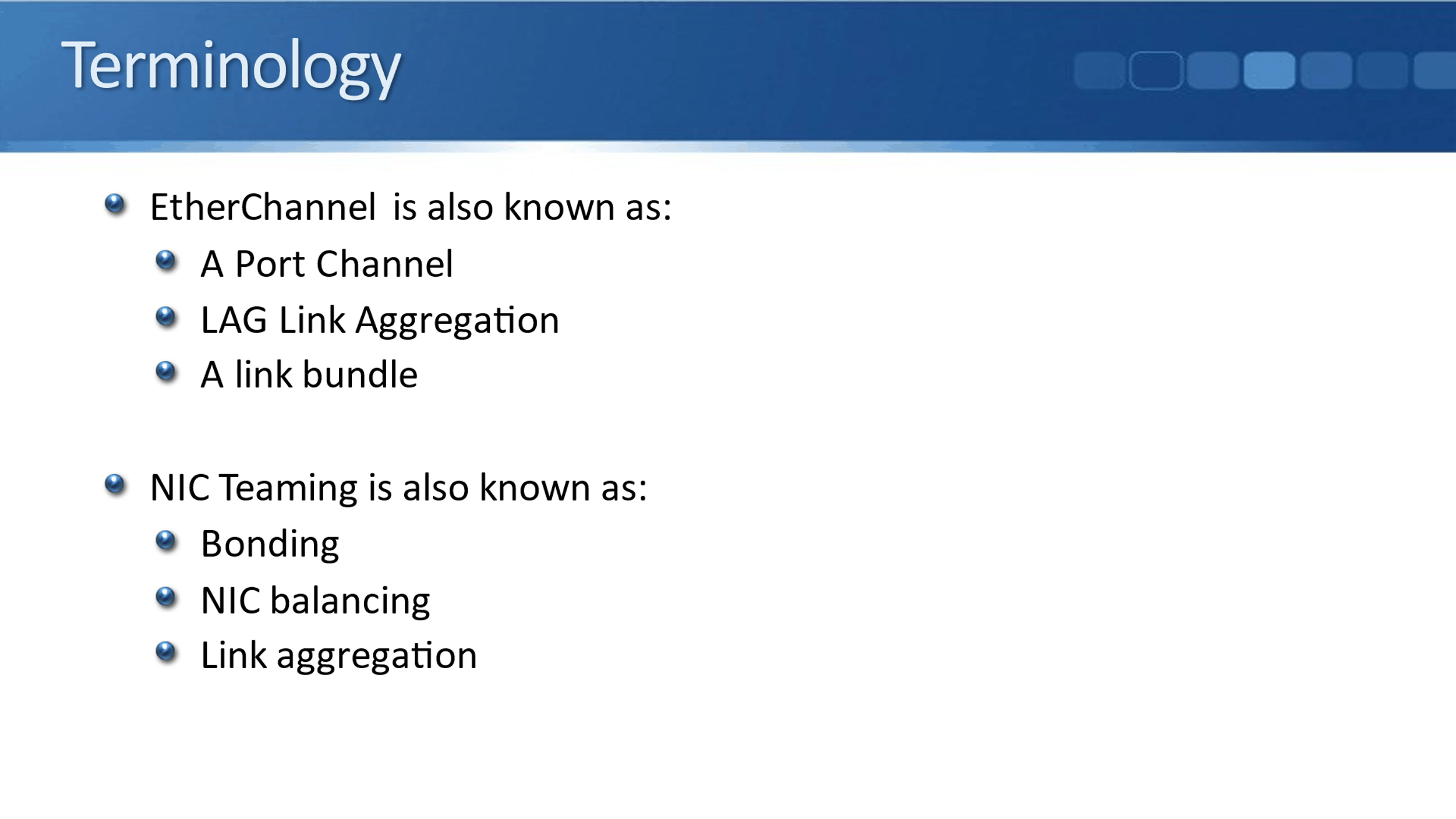
I'm putting this information in here as well because I wanted to explain the terminology to you and let you know that there's several different names for what's basically the same thing. EtherChannel on our switches is also known as:
- Port Channel
- Link Aggregation (LAG)
- Link Bundle
When we bundle our physical interfaces on our servers, we'll usually call it NIC Teaming, it can also be called:
- Bonding
- NIC Balancing
- Link Aggregation
Additional Resources
Implementing EtherChannel in a Switched Network: https://www.ciscopress.com/articles/article.asp?p=2348266&seqNum=3
Etherchannel on Cisco IOS Catalyst Switch: https://networklessons.com/switching/etherchannel-cisco-ios-catalyst-switch
Configuring and Verifying EtherChannel: https://www.learncisco.net/courses/icnd-2/etherchannel-and-l3-redundancy/configuring-etherchannel.html
Libby Teofilo

Text by Libby Teofilo, Technical Writer at www.flackbox.com
Libby’s passion for technology drives her to constantly learn and share her insights. When she’s not immersed in the tech world, she’s either lost in a good book with a cup of coffee or out exploring on her next adventure. Always curious, always inspired.