This guide has complete step by step instructions to help you setup a home lab for VMware SRM Site Recovery Manager with the NetApp Snapmirror Data Protection solution. Everything is free and because it’s virtualized you can run it all on your laptop.
Lab Guide by Vincent Li.

You can contact him via email at
And connect on LinkedIn at https://www.linkedin.com/in/bestvincent/
Table of Contents
2. Lab Diagram, Software and Networking
2.3 Networking and IP Addresses
2.4 VMware Workstation Virtual Network
3. Prepare Virtual Infrastructure
3.1 Build an Active Directory Server
3.5 Build and Configure SRM/SRA Server
4.1 Build ONTAP Server add it to vCenter VSC
4.2 Configure NetApp environment for NFS and iSCSI
4.4 Configure an NFS volume with Snapmirror Data Protection
4.5 Configure on ESX/vCenter to mount NFS volume
4.5.1 Configure VMkernel Network Adapter for NFS/iSCSI
4.5.2 Configure ESX to mount NFS volume
4.6 Configure an iSCSI lun with Data Protection for ESX
4.6.1 Enable iSCSI – connections from initiator to iSCSI Target
4.6.2 Configure an iSCSI volume with Data Protection
5. Configure SRM for Disaster Recovery
5.2 Configuring inventory mappings
5.2.1 Create resource mappings
5.3 Configure placeholder datastore
5.4 Configure array manager and enable array pair
6.2 Cleanup after Test Recovery Plan
6.3 Run Recovery Plan (Prod Site failover to DR Site)
6.4 Reprotect (Sync from DR Site to Prod Site)
6.5 Run Recovery Plan (DR Site failover to Prod Site)
6.6 Reportect (Sync from Prod Site to DR Site)
Kashif Ali

I have never seen any training course in Netapp the way Neil conducted this and the way he breaks down every concept is like watching a movie…I am feeling so motivated and pumped up to retain all this knowledge…thank you!
Introduction
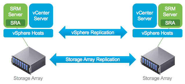
VMware vCenter Site Recovery Manager (SRM) is a business continuity and disaster recovery solution that helps you to plan, test, and run the recovery of virtual machines between a protected vCenter Server site and a recovery vCenter Server site.

There are a lot of storage vendors for enterprise: Dell/EMC, Hitachi Vantara, NetApp etc. Each vendor has their own data protection solutions. NetApp SnapMirror is a feature of ONTAP that enables you to replicate data from one array system at your Production Site to another array system at the DR Site.
VMware SRM combined with NetApp Snapmirror Data Protection is a perfect solution for customer’s VMs Disaster Recovery and Migration. In a real world, it may take months or even a year to set this up, test it and implement the whole solution. Depending on the role of your job in the company, you may not have the chance to get your hands on for implementation.
Let’s start and get our hands dirty .
Lab Diagram, Software and Networking
Lab Diagram
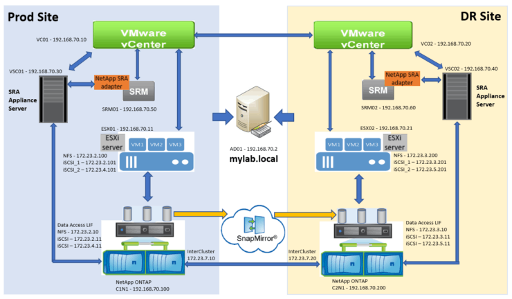
In the lab environment, we will set up the following:
- Two Data Center sites: Prod Site and DR site
- One shared Active Directory Server (for simplicity)
- Two ESXi servers – one at Prod, one at DR
- Two vCenter Servers – one at Prod, one at DR
- Two SRM/SRA servers – one at Prod, one at DR
- Two SRA Appliance Servers – one at Prod, one at DR
- Two NetApp ONTAP Simulator Servers – one at Prod, one at DR
List of Software
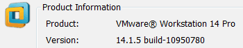
As I mentioned earlier, everything in this lab is virtualized - server, network and storage. My Laptop is Lenovo ThinkPad W541, Windows 7 Enterprise with 32 GB of ram. Server virtualization software is VMware workstation 14 Pro
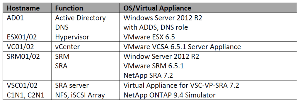
The below table has the software information you need to build this lab.
Networking and IP Addresses
In order to keep it simple, the following subnets are used in this lab:
- Management Network: 192.168.70.0/24
- InterCluster Network – for Snapmirror replication: 172.23.7.0/24
- Data Network – for NFS and iSCSI path 1 access: 172.23.2.0 (Prod Site)
- Data Network – for iSCSI path 2 access: 172.23.4.0 (Prod Site)
- Data Network – for NFS and iSCSI path 1 access: 172.23.3.0 (DR Site)
- Data Network – for iSCSI path 2 access: 172.23.5.0 (DR Site)
- Cluster network – 169.254.x.x
Below is the IP addresses table and you also can see IP information in the above diagram.
| Default Gateway | Subnet x.x.x.1 |
| AD01 | 192.168.70.2 |
| VC01 | 192.168.70.10 |
| VC02 | 192.168.70.20 |
| ESX01 | 192.168.70.11 |
| ESX02 | 192.168.70.21 |
| VSC01 | 192.168.70.30 |
| VSC02 | 192.168.70.40 |
| SRM01 | 192.168.70.50 |
| SRM02 | 192.168.70.60 |
| NetApp Cluster1 | 192.168.70.100 |
| NetApp Cluster1 Node1 (C1N1) | 192.168.70.101 |
| C1N1_NFS01 | 172.23.2.10 |
| C1N1_iSCSI01 | 172.23.2.11 |
| C1N1_iSCSI01 | 172.23.4.11 |
| ESX01 vmk1 (for NFS) | 172.23.2.100 |
| ESX01 vmk2 (for iSCSI path1) | 172.23.2.101 |
| ESX01 vmk3 (for iSCSI path2) | 172.23.4.101 |
| NetApp Cluster2 | 192.168.70.200 |
| NetApp Cluster2 Node1 (C2N1) | 192.168.70.201 |
| C2N1_NFS01 | 172.23.3.10 |
| C2N1_iSCSI01 | 172.23.3.11 |
| C2N1_iSCSI01 | 172.23.5.11 |
| ESX02 vmk1 (for NFS) | 172.23.3.200 |
| ESX02 vmk2 (for iSCSI path1) | 172.23.3.201 |
| ESX02 vmk3 (for iSCSI path2) | 172.23.5.201 |
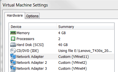
VMware Workstation Virtual Network
Based on our lab design and subnets plans, we need create Virtual Networks (VMnets) on VMware Workstation. The below screenshot is from my laptop. When you build a new VM, please look for the VM network requirements and you may need to add more than one network adapter.
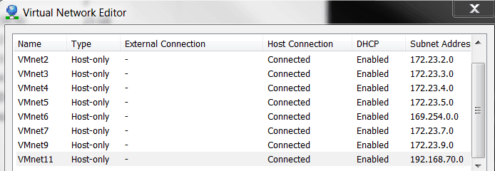
For example, ESX01 needs network 192.168.70.0 (for Management), 172.23.2.0 (for NFS and iSCSI access – path #1), 172.23.4.0 (for iSCSI access – path #2). Thus, we need add three network adapters with connections to VMnet11, VMnet2 and VMnet4 per below screenshot.
For more information please see the 'VMware Workstation Professional' chapter in How to Build a NetApp ONTAP 9 Lab
Prepare Virtual Infrastructure
Build an Active Directory Server
As a start, we will build our Active Directory and DNS server first. Once it is ready, other VMs in this lab will point to its IP address as DNS for name resolution and/or join the server to Active Directory domain.
For step by step instructions to install and configure a Windows Active Directory Domain Controller server, please see the 'Windows Server Build' chapter of How to Build a NetApp ONTAP 9 Lab. Configure the Domain Controller with the settings in this section for this lab.
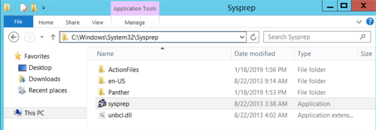
1. Build a Windows Server template
Take all the default settings when building the Windows Server (I use server 2012 R2 in my lab). Once the VM is installed you can login with administrator account.
Go to C:\Windows\system32\Sysprep directory and double click on sysprep.exe file
Select options as below. By doing this, each new VM cloned from this VM will use a unique SID and you won’t get any issue when joining it to the Active Directory domain.
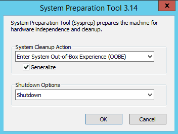
VM is powered off and this VM will be used as Windows Server build template – for AD01, SRM01 and SRM02 in our lab.
2. Clone Windows Server Template and put AD01 as VM name
3. Power on VM and login to setup the following:
- Static IP address (192.168.70.2 – in my lab)
- DNS Server – put its own IP address
- Hostname (AD01 – in my lab)
4. Install ADDS and DNS Role and promote it as Domain Controller of mylab.local domain (in my lab)
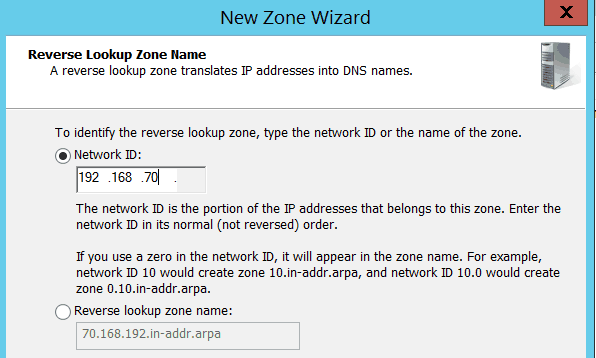
Notes: when server is rebooted and started up, go to DNS tool and add a reverse lookup zone. This will allow us to register PTR record when adding a new Host A record in DNS.
We've completed the build for AD01 – Active Directory server.
Build ESX Server
Now let’s build our ESX server, one at Prod Site (ESX01) and one at DR site (ESX02)
Please make sure you have downloaded the software from VMware, you can download a free evaluation. In this lab, the file I used is VMware-VMvisor-Installer-6.5.0-4564106.x86_64.iso (I believe it was the first release of ESX 6.5 – which I downloaded two years ago).
1. Add a new VM and mount the ESX iso file. Please note: For all the servers we are creating in this lab, VM nic1 is always assigned to VMnet11 (192.168.70.x) – for Management network.
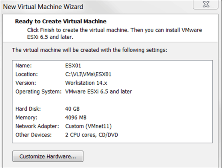
2. Power on the VM and take all the default settings to start installation
3. Once ESX server is started up, it will get an IP address from 192.168.70.x network via DHCP. We will change it to a static IP address shown in the picture below by pressing F2 on the VM console
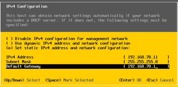
4. Set DNS and Hostname as well – which is the 192.168.70.2 IP address of AD01 we just built
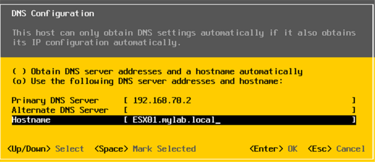
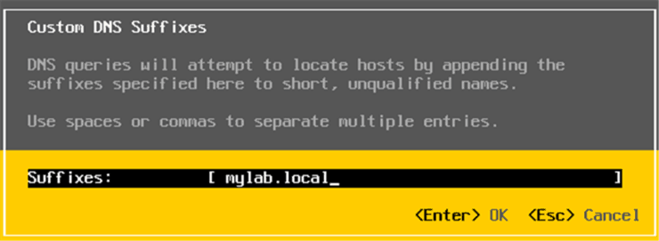
5. Customize DNS suffixes
6. Apply changes and reboot ESX. After reboot, you can see below screen on the console
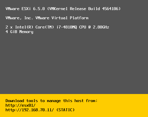
Repeat the same steps to build ESX02 for DR site.
Now we completed ESX servers build.
Build vCenter Server
Next, let’s build our vCenter server.
Initially I planned to download and deploy the newest VCSA (vCenter Server Appliance) version 6.7 – and actually I tried installation. vCenter itself is functioning well, but it has an issue working with NetApp VSC 7.2.
vCenter 6.5 support by VSC 7.2. is fine: NetApp VSC plugin shows up in vSphere Web Client (Flex/Flash) and in HTML5 client and is working as expected, even in German HTML5 client (using the latest Fling appliance 3.39).
vCenter 6.7 support by VSC 7.2 is terrible: It does not show up in Flex Client, but it shows up in HTML5 client home menu as "app.name" when HTML5 client displays German language. With an English browser it shows up as "Virtual Storage Console".
Because of that, I’m giving up use of VCSA 6.7 in our lab and back to VCSA 6.5 Update 1 version.
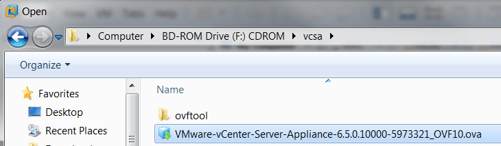
1. Mount the VCSA iso file and go to virtual CDROM drive vcsa directory, open the ova file in VMware Workstation
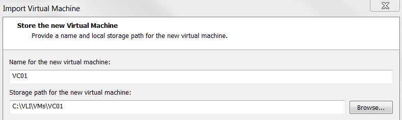
2. Change VM name to VC01 and click Next
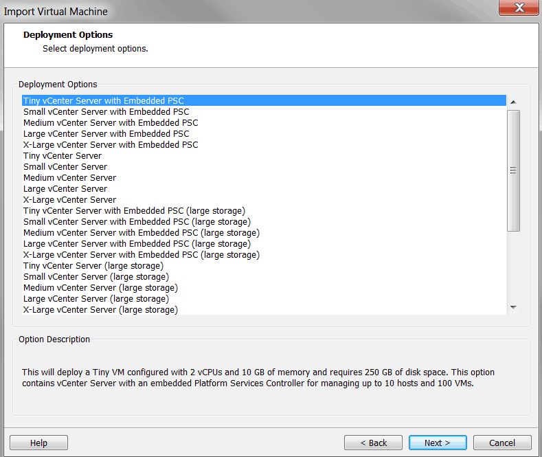
3. For our lab testing, we select Tiny vCenter Server with Embedded PSC
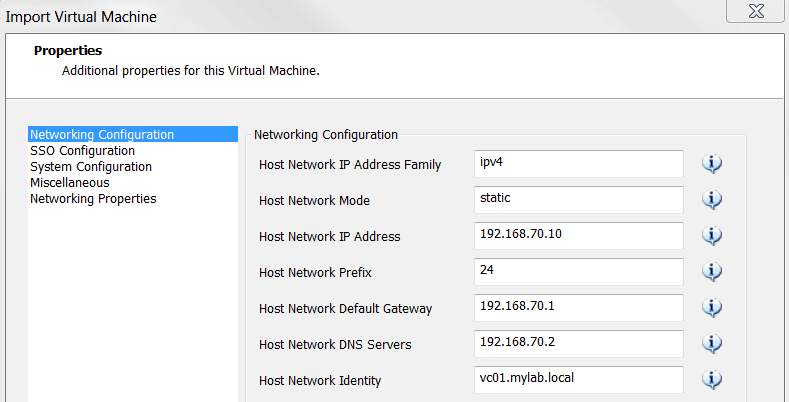
4. Fill in the Networking Configuration as shown in the picture below:
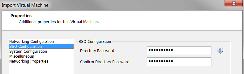
5. Fill in the SSO Configuration
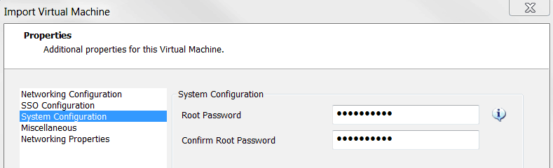
6. Fill in the System Configuration
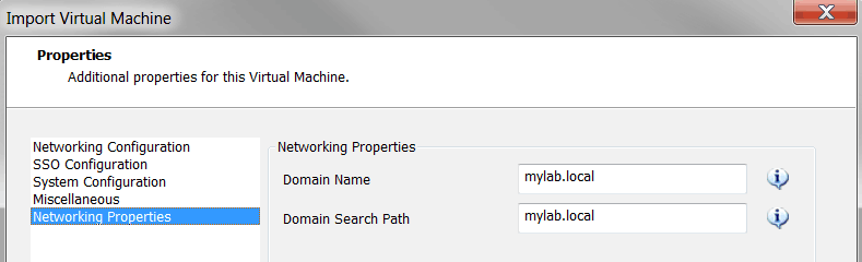
7. Fill in the Networking Properties
8. Click on Import
VM will be powered on after import is done. Please note here – we need to reset the root password before we boot the VCSA – otherwise the installation won’t be successful! VCSA 6.5 enforces a root password expiration of 365 days from the appliance OS build time.
For more information - https://kb.vmware.com/s/article/51124
9. Reset the root password of VCSA
Here are the steps to follow to reset the root password.
https://kb.vmware.com/s/article/2147144
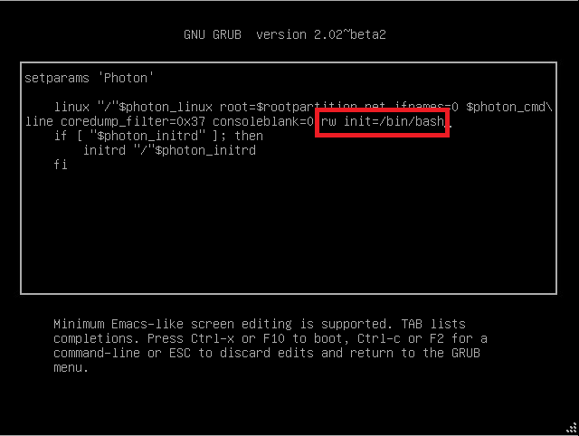
Press ‘e’ when VM is booted up and it will go to GRUB edit menu
Put ‘rw init=/bin/bash’ in the end of the line beginning with ‘linux’
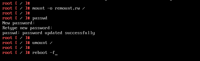
Follow below steps to reset root password
9. After VCSA server is built - it may take quite a while to complete all the steps.
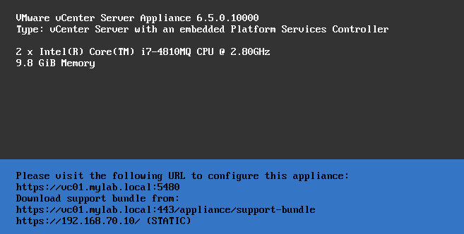
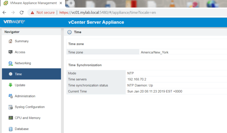
10. Login to the Web UI for Appliance Management
URL – https://vc01.mylab.local:5480 Use root to login
You can set up the NTP server there
11. Login to vCenter via URL: https://vc01.mylab.local
Use to login
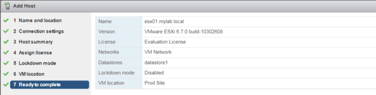
Add ESX01 host to vCenter
Repeat the same steps to build VC02 for DR site.
We completed the build for vCenter servers.
Build VSC Server
Please note, I had trouble when I tried deploying VSC server appliance directly into VMware Workstation. The work around is – deploy it to virtualized ESX first (virtual on virtual ) and export the VM from ESX server to OVF format. Then open the OVF file from VMware workstation - I didn’t have issues doing it that way.
1. Ensure ESXi server has enough capacity on Datastore (I added 100 GB as new Datastore)
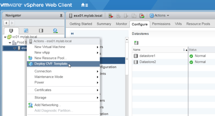
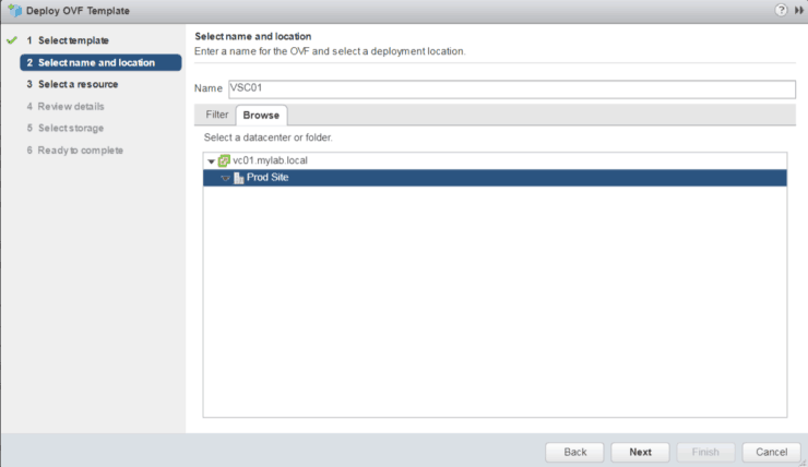
2. From vCenter, right click on ESX01, select “Deploy OVF Template”
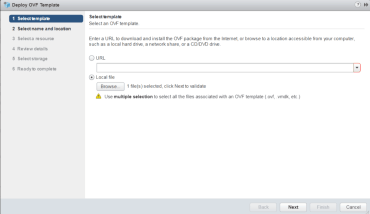
3. Browse and select the ova file we downloaded from NetApp
4. Put VM name and location
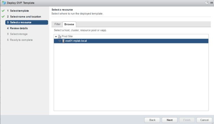
5. Select ESX Host
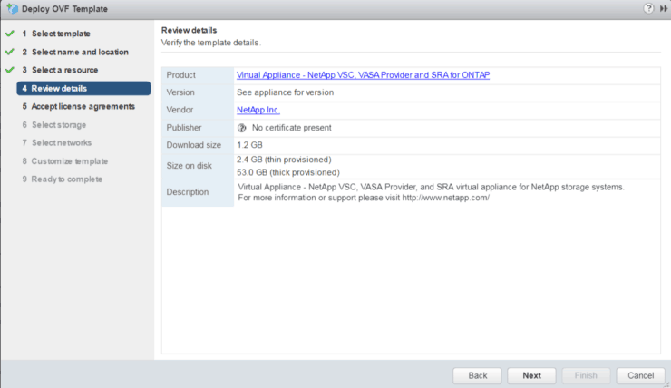
6. Review appliance details
7. Select Datastore and “Thin Provision” for virtual disk format

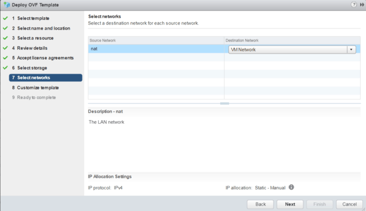
8. Select Network for VM
9. Customize template
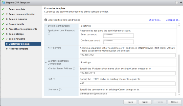
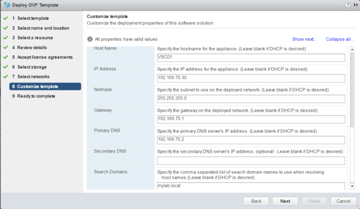
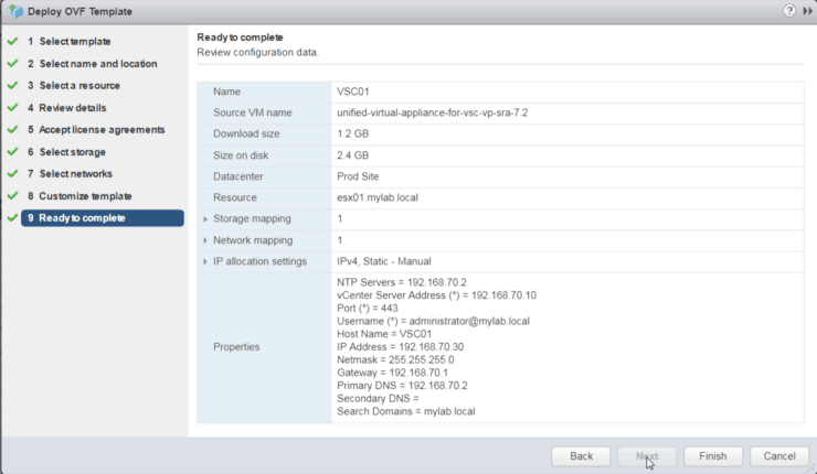
10. Final review and ready to complete
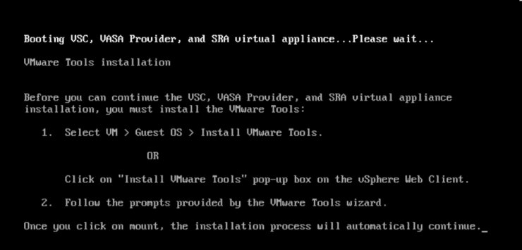
11. Power on VM and follow the instructions to install VMware Tools
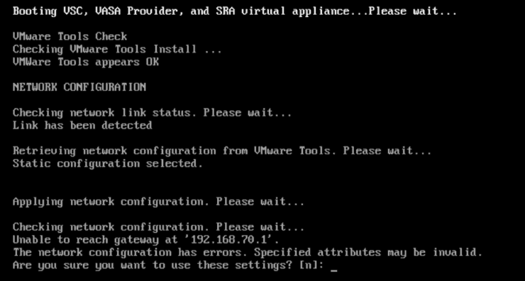
12. I got error message for default gateway. Just ignore it by pressing Y for the question “Are you sure you want to use these settings?”
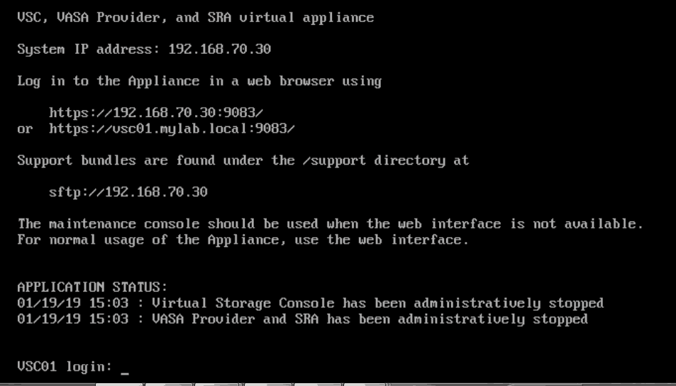
13. In the end, you will see below screen when installation is done
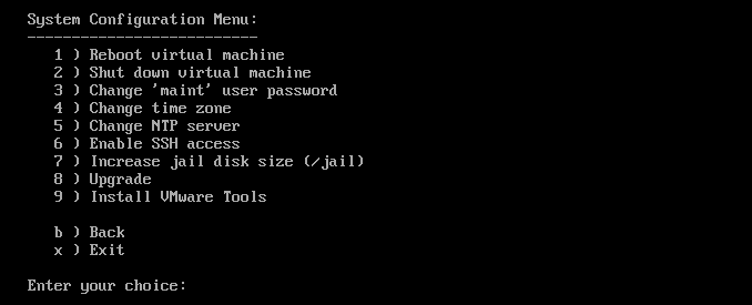
14. Login as maintenance account – maint/admin123 to console
From main menu, select option 2 – System Configuration
Select 2 – Shut down virtual machine
15. Once VSC is powered off on ESX server, we will export this VM to OVF template
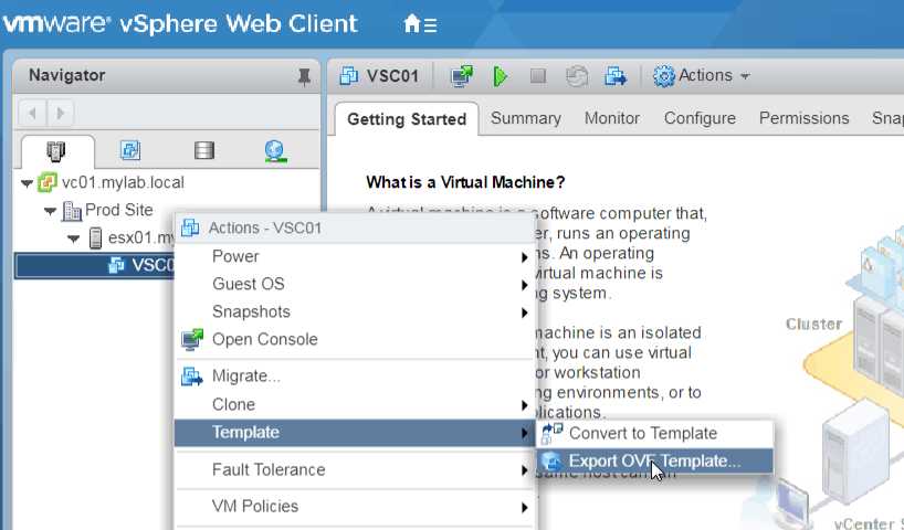
16. Once VM is exported we can use VM Workstation to open the OVF file we saved
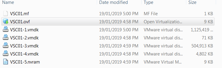
17. Boot the VSC server in VMware Workstation
Here we will review the network configurations one more time
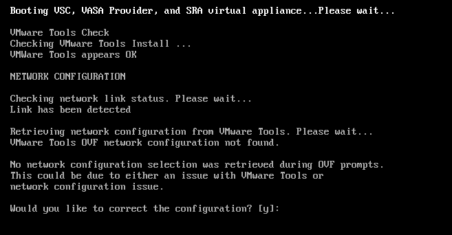
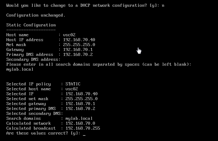
18. When VSC is booted up and ready to login – use maint/admin123 login
Verify Application Service Status
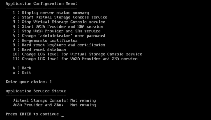
Press 2 to start the Virtual Storage Console service

Press 4 to start VASA Provider and SRA service

Press 1 to verify one more time

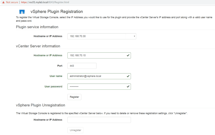
19. Register VSC plugin to vCenter
https://192.168.70.30:8143/Register.html (IP address is your VSC server IP or use FQDN)
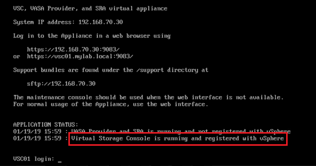
20. Login back to VSC console and we will see VSC is running and registered with vSphere
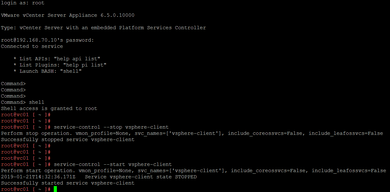
21. Restart vCenter Web Client service
Login to vCenter server console with root
Type shell to launch bash
Follow below screenshot to restart vSphere web client service
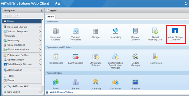
22. Login to vCenter via the Web Client
Now we can see NetApp VSC icon is showing up
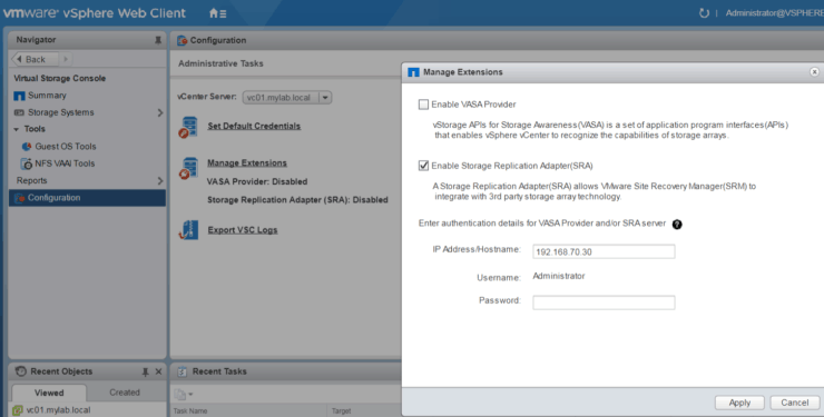
23. Enable SRA from Virtual Storage Console
Go to VSC Configuration - Manage Extensions
Enable Storage Replication Adapter (SRA)
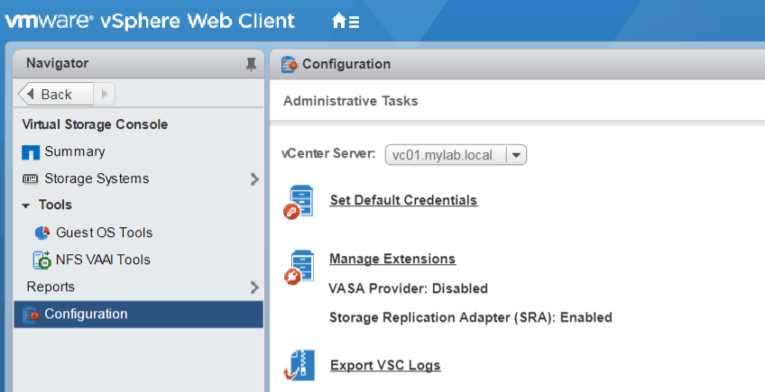
24. Logout from vCenter Web UI and re-login
Confirm SRA is enabled
Now we have built the VSC server and registered VSC to vCenter successfully.
Build and Configure SRM/SRA Server
Now it is time to build the SRM server
1. Deploy Windows server 2012 R2 from the template we saved earlier
2. Set up hostname, IP address and join server to mylab.local domain
3. Copy the following two files over to SRM server
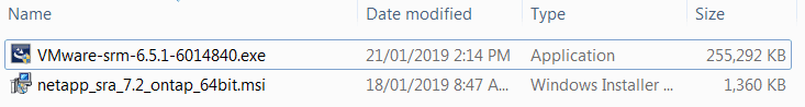
Installing SRM
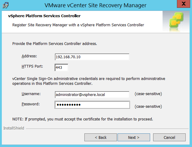
1. Double click on VMware-srm-6.5.1-xxxxxxx.exe file to start SRM installation
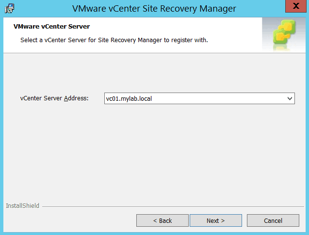
Select all defaults for past steps. We need to provide vCenter IP Address and SSO credentials:
2. Accept Certificate from vCenter and verify vCenter hostname
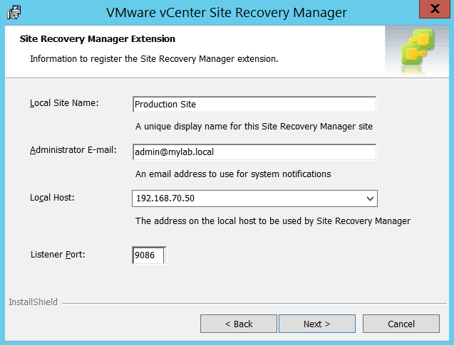
3. Fill in information to register SRM extension
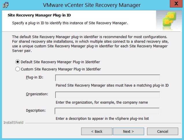
4. Use default SRM Plug-in Identifier
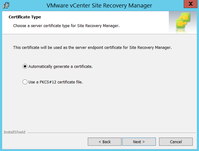
5. Use Automatically generate a certificate
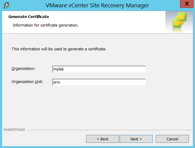
6. Fill in Organization and OU name
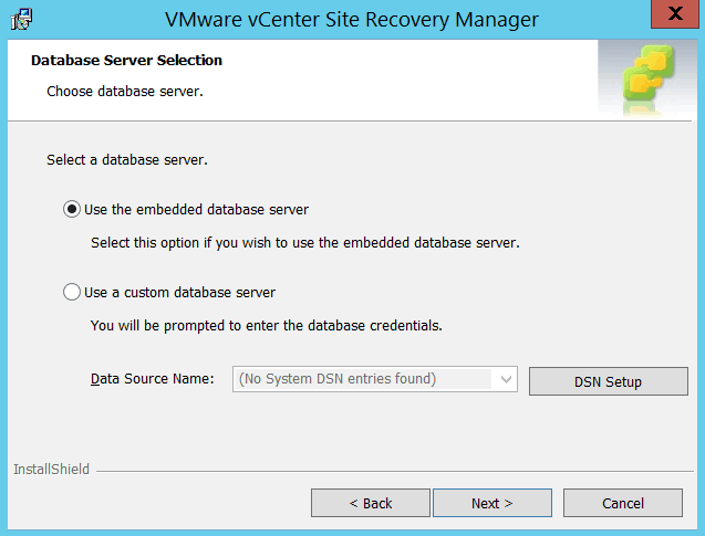
7. Select to use embedded database server
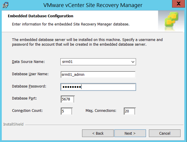
8. Enter information for embedded SRM database
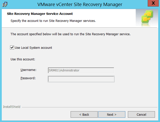
9. Use local system account
10. Click on Install
11. Installation completed successfully
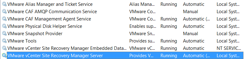
12. Go to Services MMC and verify SRM and SRM Database services are up and running
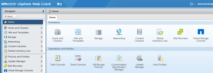
13. Login to vCenter web client, now we can see Site Recovery icon is added to inventories
Installing SRA
Now let’s go ahead installing another component SRA on the same SRM server. This is the requirement for SRM implementation by VMware.
1. Double click on SRA installer file

2. Click next on welcome screen
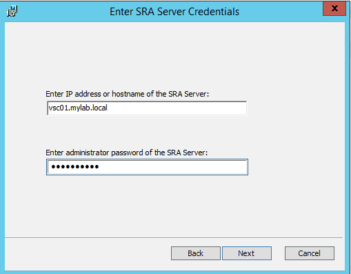
3. Enter SRA Server credentials – basically here we need put the VSC virtual appliance server we built already.
4. Click on Install
5. Installation completed
6. Verify SRA is installed
Login to vCenter web client Site Recovery Sites click on ‘vc01.mylab.local’ (name could be different – depends the site name you put during SRM installation) Go to Monitor tab and SRAs below
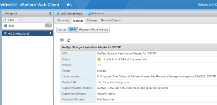
This completes the SRM and SRA installation.
Repeat the same steps for SRM and SRA setup at DR Site.
We've now prepared the whole virtual infrastructure which has the following components:
- One shared Active Directory server;
- 2 ESX Servers (one at each site)
- 2 vCenter servers (one at each site)
- 2 NetApp VSC servers (one at each site)
- 2 SRM/SRA servers (one at each site)
We added ESX servers to respective vCenter servers at both sites, we also registered SRM and VSC plugins to vCenter, and SRA is enabled on VSC.
We’re almost there. Let move forward to build NetApp storage.
Prepare NetApp Environment
We need to build an environment for storage which VMware ESX is able to use. For NetApp, NFS, iSCSI, FC/FCoE – all 3 protocols are supported by VMware. * FC/FCoE is out of scope for this Lab.
Let’s get started on building it.
Build ONTAP Server and add it to vCenter VSC
You can find step by step instructions to download, install and configure the ONTAP simulators in the 'ONTAP Simulator Build' chapters of How to Build a NetApp ONTAP 9 Lab
I’m going to assume you have followed the steps in the eBook and have built two ONTAP Clusters– one at each site. To keep our lab simple I'm using only one node in each cluster.
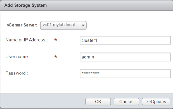
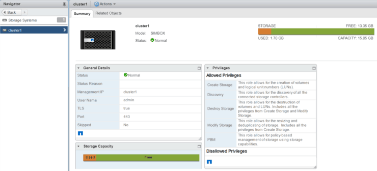
After NetApp ONTAP is up and running, we can add it to VSC on vCenter as a storage system.
1. Login to vCenter via Web Client
2. Go to NetApp VSC, we will add NetApp cluster to vCenter
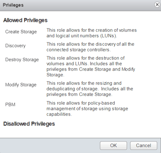
3. Review allowed privileges and click OK
4. Cluster1 added storage system
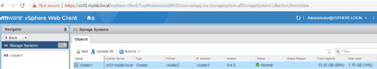
Do the same steps at DR site.
Configure NetApp environment for NFS and iSCSI
After the simulator has started up, login to NetApp OnCommand System Manager. Some additional setup may by required, e.g. setup Time Zone and NTP server, install required licenses for NFS, iSCSI and Snapmirror etc.
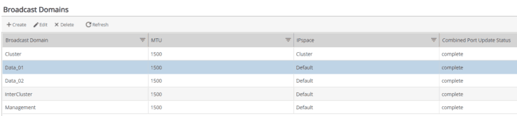
1. Create Broadcast domains for InterCluster, Data_01 and Data_02. Make sure you select the correct physical ports for each broadcast domain.
- Data_01 is for NFS and iSCSI path 01 access on 172.23.2.0 network
- Data_02 is for iSCSI path 02 access on 172.23.4.0 network
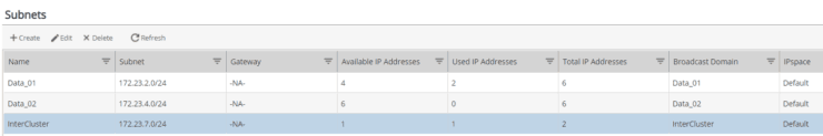
2. Create subnets and assign the respective broadcast domain for each subnet.
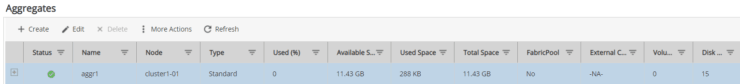
3. Create Aggregate
4. Create SVM (Storage Virtual Machine)
To keep it simple, we are going to use the same SVM for both NFS and iSCSI – so make sure to select both protocols when creating the SVM.
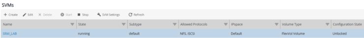
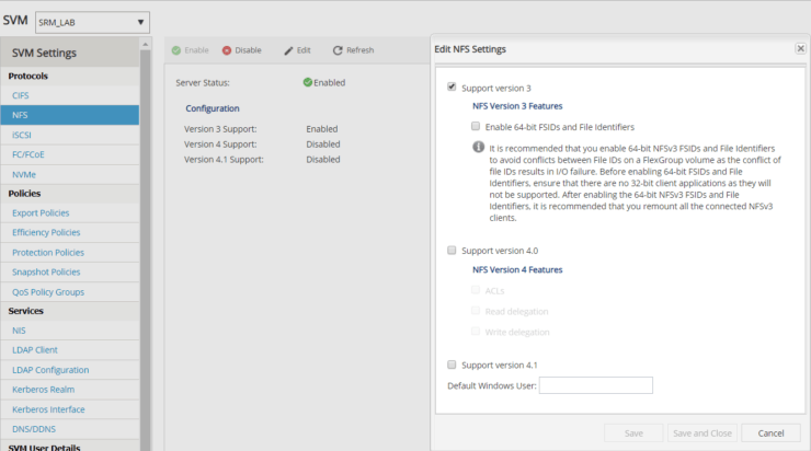
Please note: one extra step for ONTAP 9 is – go to SVM settings and enable NFS service.
5. Create logical network interfaces for InterCluster connection, for NFS, for iSCSI (need 2)
Interfaces name and IP addresses are listed below.
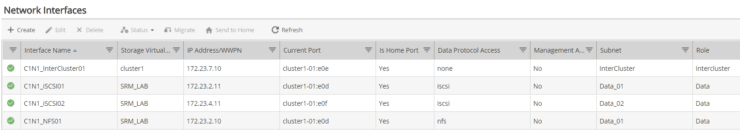
To make sure all network interfaces are up and running, you can do a ping test to each IP address.
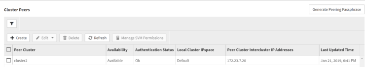
Create Cluster Peer
Now we’re ready to make connections for both Clusters via InterCluster interfaces. In a real world, the link will be two data centers via DWDM, FCIP etc. The Snapmirror data traffic will pass through this pipe.
1. Go to C1N1 OnCommand System Manager Configuration Cluster Peers Create
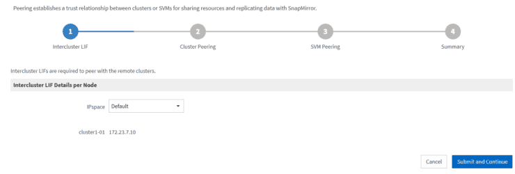
2. Provide target cluster InterCluster LIF IP address
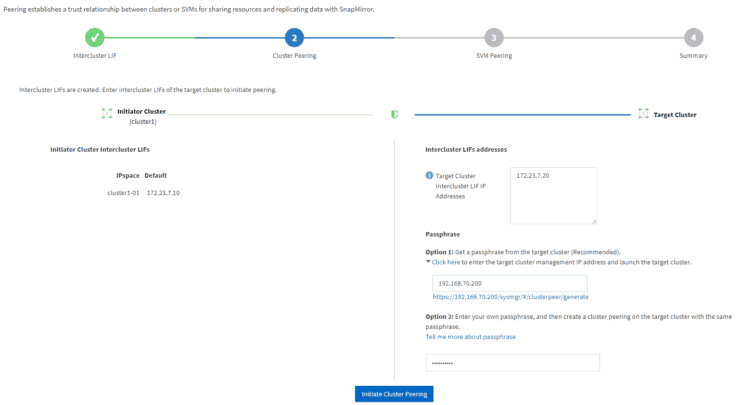
3. Generate a passphrase for Cluster peering
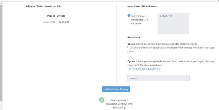
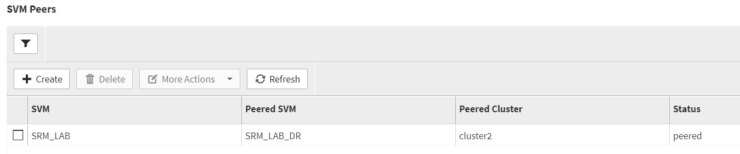
4. After Cluster peering is successful, we will validate SVM peering
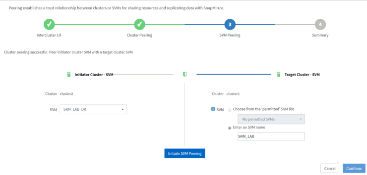
5. Both Cluster peering and SVM peering are successful
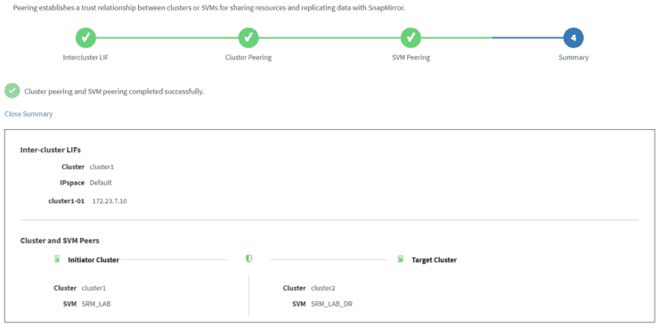
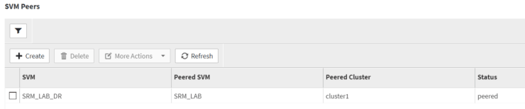
6. Finish and verify from both sides

And SVM peers are good as well.
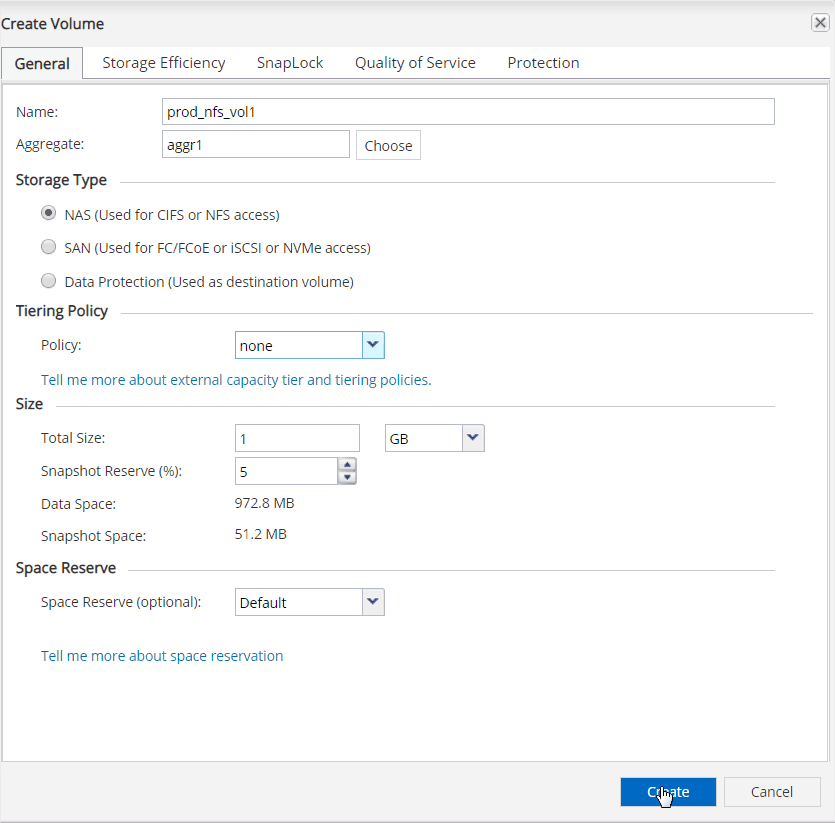
Configure an NFS volume with Snapmirror Data Protection
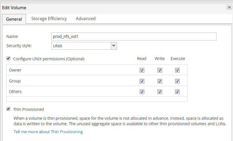
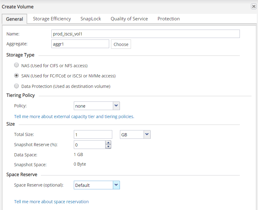
1. Go to Volume under SVM “SRM_LAB”
Click on Create
Use the following fields:
- Volume name
- Aggregate
- Storage type: NAS (used for NFS)
- Tiering Policy: None
- Size: 1 Gb
- Space Reservation: Default
2. To avoid permission issue in our lab, we grant all read/write access for all the users and groups
3. We also edit the default export policy by add a rule to allow any client’s access for NFS

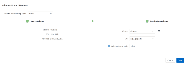
4. Enable Data Protection with Snapmirror
Under Volumes, select the NFS volume, More Actions and Protect

5. Input the following options for Snapmirror
- Volume Relationship Type: Mirror
- Cluster: Cluster2 (Default)
- SVM: SRM_LAB_DR
- Volume Name Suffix: _dest (basically on target cluster, it will create a DP volume with original source volume’s name plus this suffix in the end)
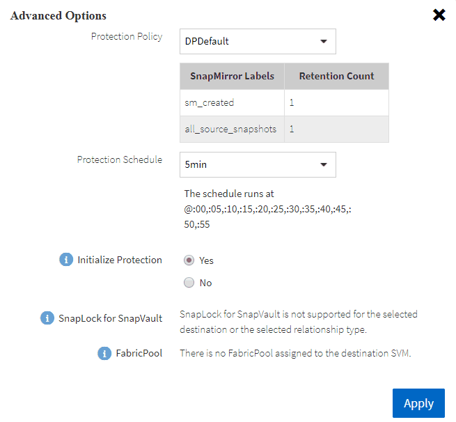
Also, there are a few advanced options for Protection Policy and schedules, if initialize protection or not etc.
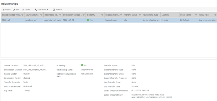
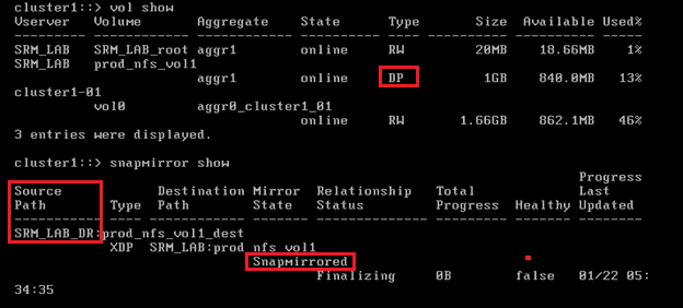
6. Verify the relationship of volume
- Is Healthy: Yes
- Relationship Status: Snapmirrored
- Transfer Status: Idle
Configure on ESX/vCenter to mount NFS volume
Configure VMkernel Network Adapter for NFS/iSCSI
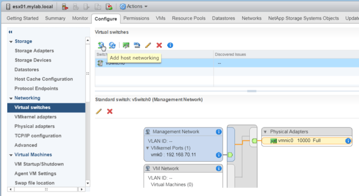
To make ESX able to mount NFS volume or connect iSCSI volume, we need to add a VMkernel Network Adapter to the ESX host.
1. Go to Configure tab, Virtual Switches, Add Host networking
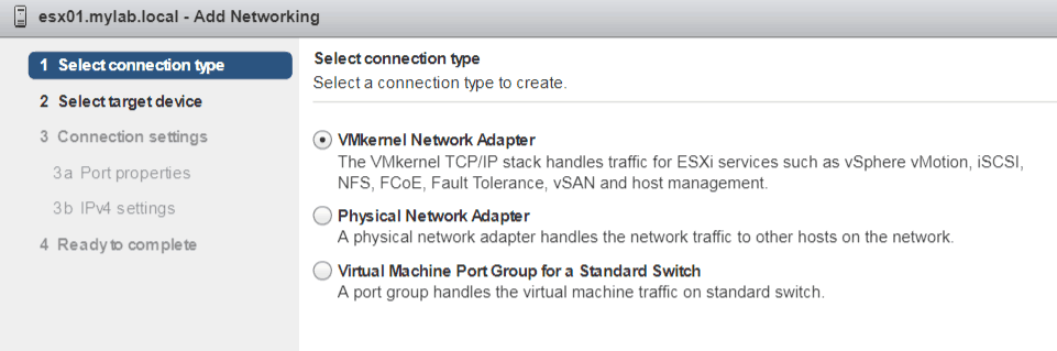
2. Select VMkernel Network Adapter
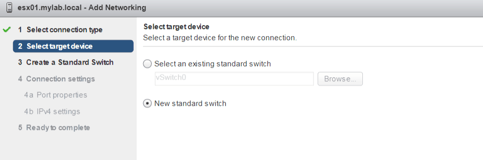
3. Select new standard switch (since the physical NIC we added to ESX servers are not used by any vSwitch)
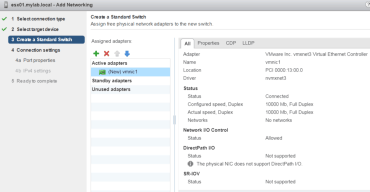
4. Add the vmnic we planned for NFS
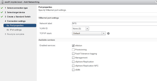
5. Give NFS as network label and enable vMotion service
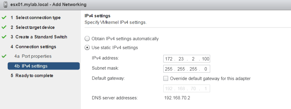
6. Input IP Address and Subnet Mask information
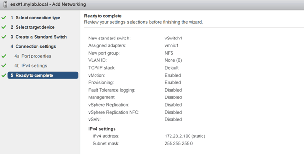
7. Review and submit
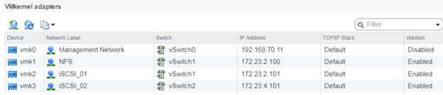
We can repeat the same steps to add additional two VMkernel interfaces for iSCSI
Configure ESX to mount NFS volume
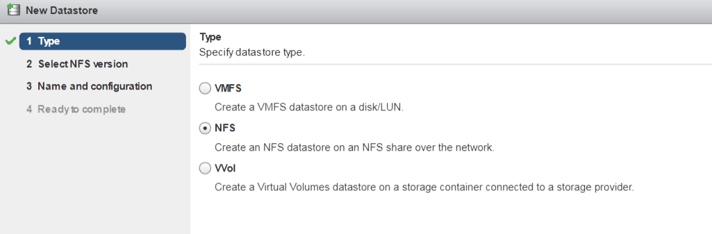
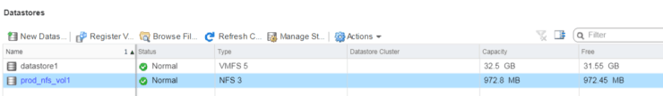
1. Go to Configure tab, Datastores, Add Datastore
Specify NFS as datastore type
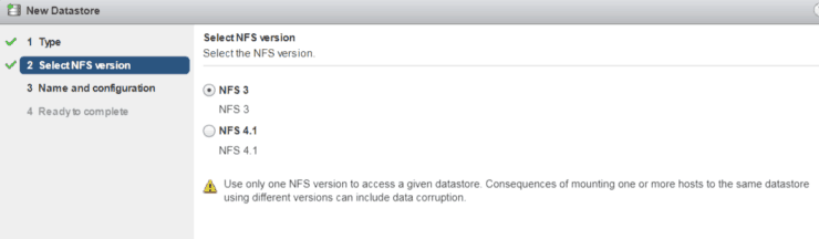
2. Select NFS v3 for our lab test
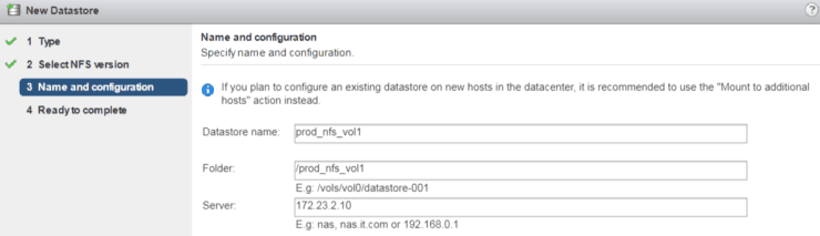
3. Fill in the following information
Datastore Name: prod_nfs_vol1
Folder: /prod_nfs_vol1 (this is the junction path on NetApp)
Server: 172.23.2.10
4. Review and Press OK
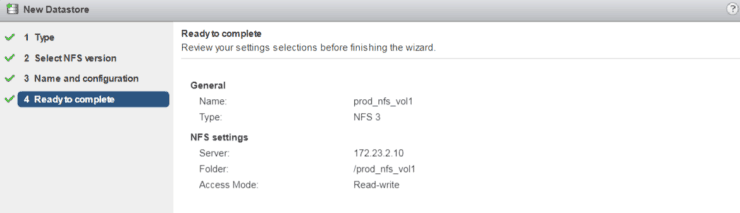
5. We can see one new NFS datastore is added and available for ESX hosts
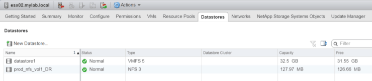
6. For DR site, we need to manually mount the replicated NFS volume.
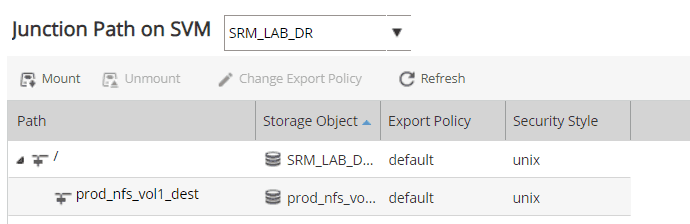
7. Add NFS as Datastore for DR NFS volume
8. Make a test for Snapmirror DP
Explore the NFS datastore at Prod Site mounted by ESX01, create a new directory or upload some files
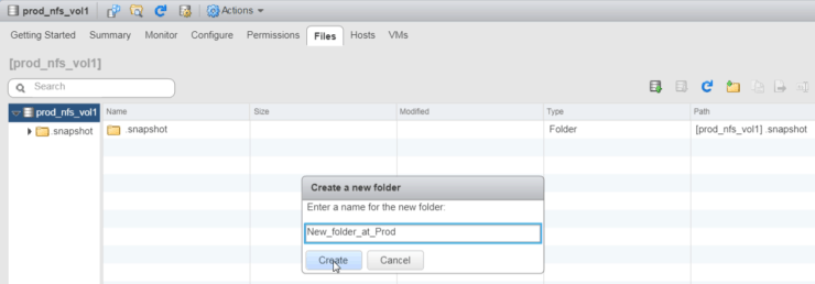
Wait for 5 minutes (because we selected 5 min for replication schedule), explore the DR NFS volume
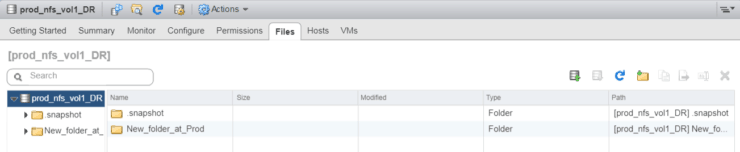
We can see the new created folder has been synced over to the DR volume.
9. Deploy a Tiny Core Linux VM to NFS datastore
To prepare SRM testing, we will deploy a very tiny (cpu, memory and hard disk is very small) VM on ESX server which is running on VMware Workstation (Virtual on Virtual )
You can find the OVA installation file by Googling for 'Tiny Linux OVA".
Deploy and power it on – the VM will get an IP address from Management network, it is a good idea run a continuous ping test during SRM fail over and fail back test.
Configure an iSCSI LUN with Data Protection for ESX
Enable iSCSI – connections from initiator to iSCSI Target
During the preparation for NFS volumes, we already created Broadcast domains, Subnets, Aggregate, SVM, LIFs for both NFS and iSCSI – thus we don’t need repeat those steps.
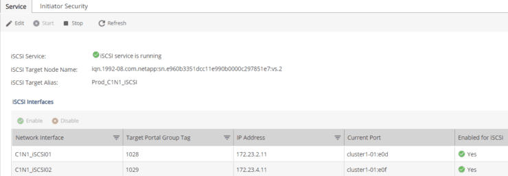
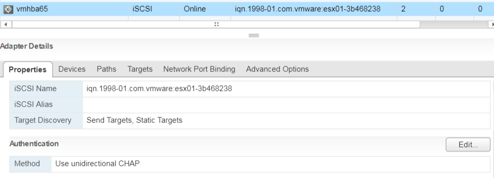
1. Edit and Start iSCSI on ONTAP
Go to SVM Settings iSCSI Start
And click on Edit to put iSCSI Target Alias name
Verify two iSCSI Network Interfaces are correct and enabled
Copy and save iSCSI Target Name for later steps
2. At VMware ESX/vCenter side, again we already prepared VMkernel Network Adapters for iSCSI – we prepared 2 adapters – this will enable each volume to have 2 paths to iSCSI Target on NetApp storage.

3. Go Configure Storage Adapters, Add new storage adapter
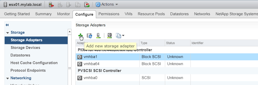
4. Select software iSCSI Adapter

And we will see a new iSCSI software adapter added to list. Save that iSCSI initiator name for future steps

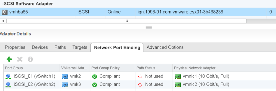
5. Bind Network ports for iSCSI
Select that iSCSI Adapter go to “Network Port Binding” under Adapter Details
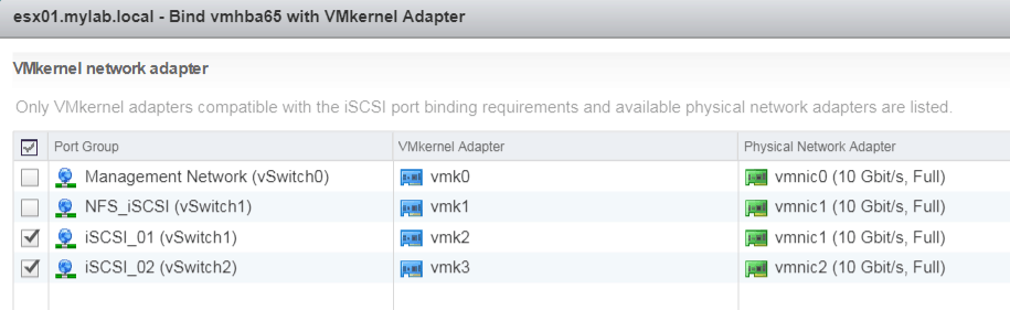
Verify after clicking on OK
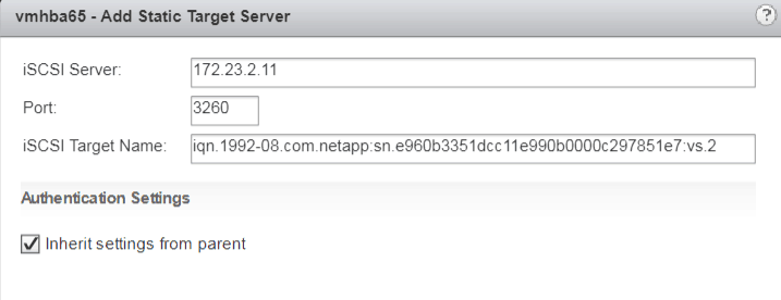
6. Add iSCSI Target
Go to Targets tab, click on Add
iSCSI Target name was saved from step #1 on NetApp
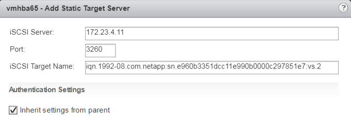
Add the 2nd iSCSI Target server
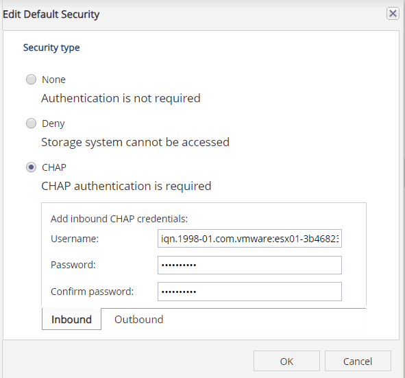
7. Enable CHAP authentication on ESX side
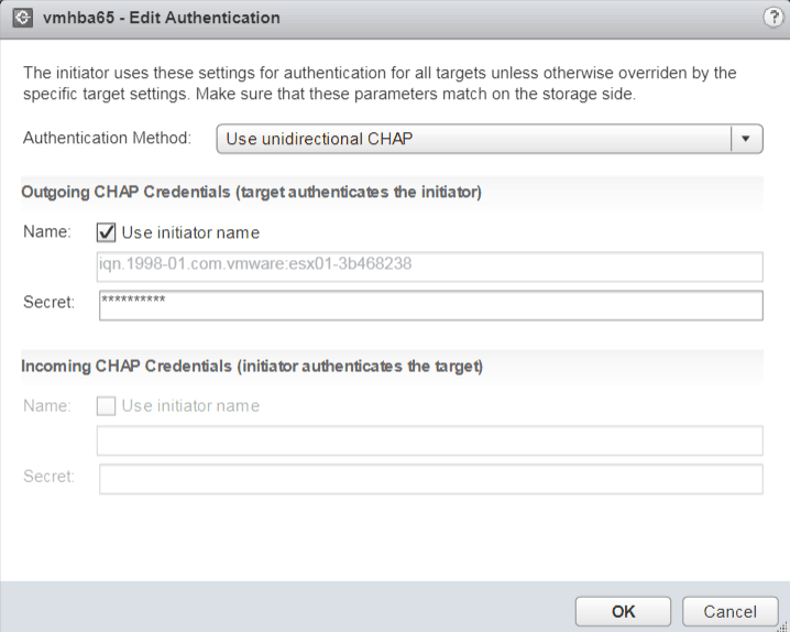
8. Enable CHAP authentication at NetApp side
User name here is ESX iSCSI adapter initiator name – which we saved before
Repeat the same steps for DR site – from iSCSI connections from initiator to Target.
Configure an iSCSI volume with Data Protection
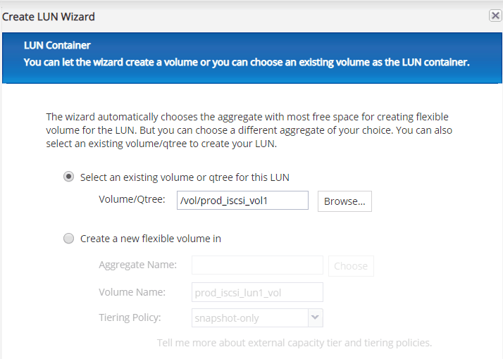
1. From NetApp OnCommand System Manger Volumes (under SVM) Create
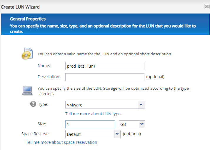
2. Create a LUN from iSCSI volume
Put a name for lun, select VMware for type
3. Select the iSCSI volume we created
4. for Initiator group, put the server’s name, OS type and iSCSI for protocol

5. On Initiator tab, click on down arrow, you should be able to see the ESX iSCSI initiator name, click Add Initiator
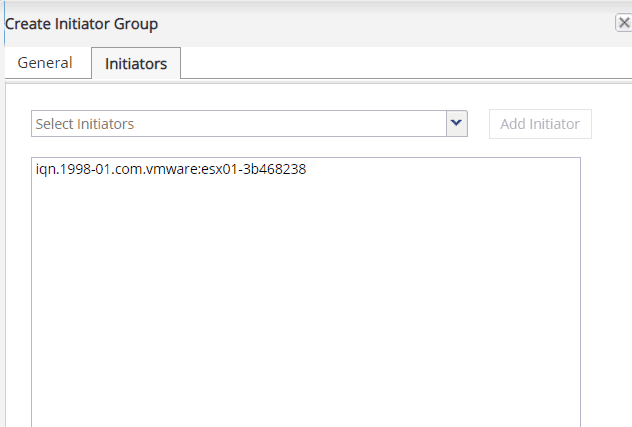
6. Make sure the igroup we created is selected
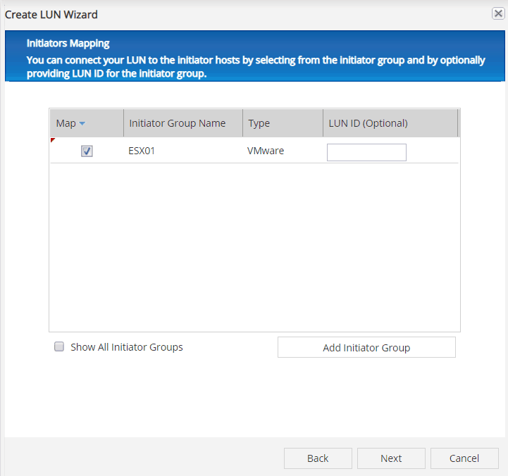
7. Finish LUN creation.
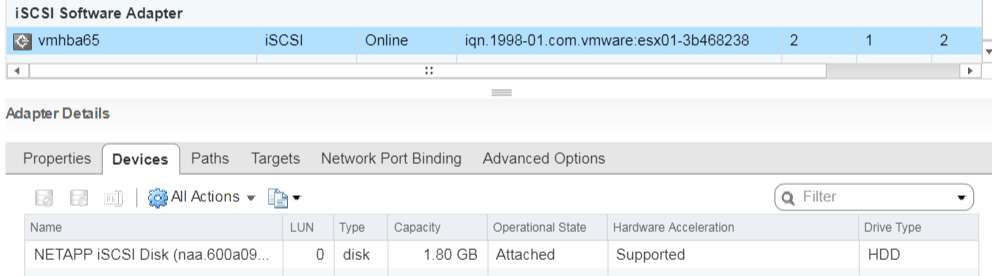
8. Now we back to ESX server and perform a rescan on iSCSI Adapter
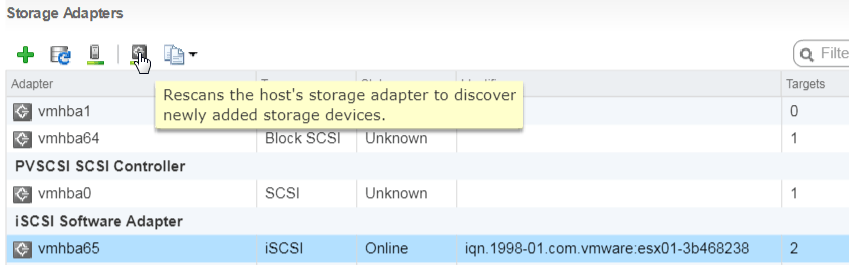
9. Now we can see iSCSI LUN is showing as new device
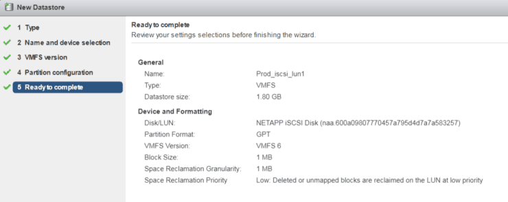
10. Add the new iSCSI LUN as VMFS datastore
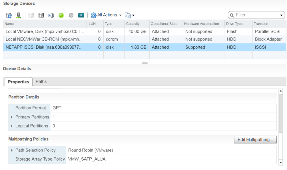
11. Also we can see the default Multipathing Policy for iSCSI LUN is Round Robin (VMware)
12. Now, let’s enable Data Protection for iSCSI volume
From OnCommand System Manager, go to Protection Relationships Create
Follow the same steps we used for NFS volume to create Snapmirror relations
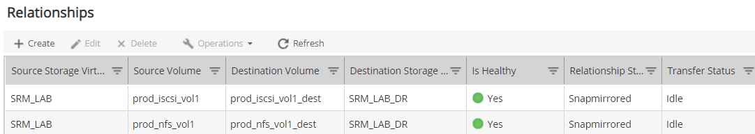
If we go to DR site of NetApp, there is a new Data Protection (DP) volume be created
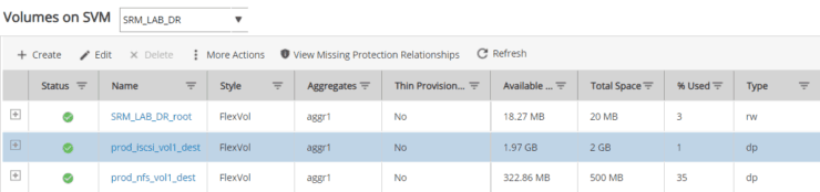
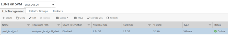
Go to LUNs, we can see a new LUN been created
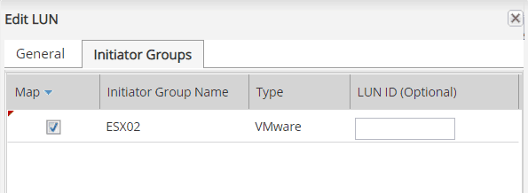
13. Click on Edit and assign ESX02 igroup for lun mapping
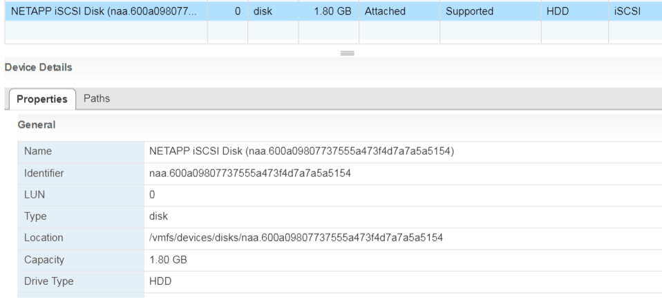
14. Back to ESX02, rescan to discover the replicated iSCSI LUN
Notes: you will see the iSCSI device, but do NOT try to add it as VMFS datastore because it is a replicated datastore from Prod site – read/write is disabled.
Configure SRM for Disaster Recovery
Finally, all the preparation work is done and we’re ready to configure SRM and make this tool work for us in an automated way.
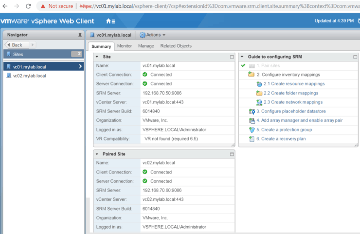
Pair Sites
As a first step, we need pair Prod Site and Dr Site. Go to SRM Sites you will see a “Guide to configuring SRM” wizard. It is very easy to follow.
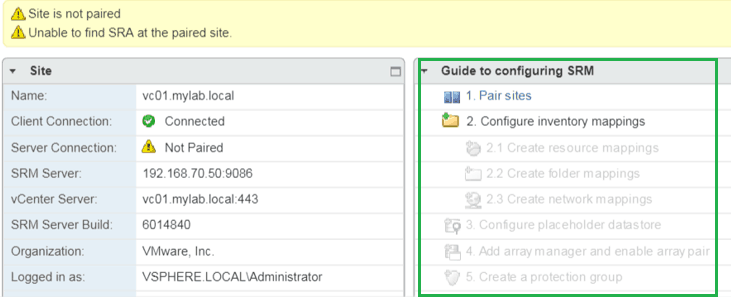
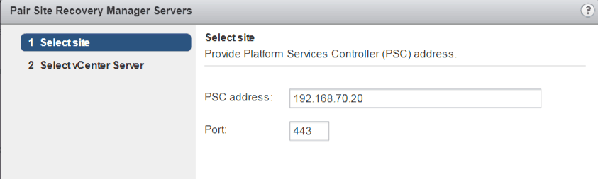
1. Click on Pair sites
Input remote vCenter IP address
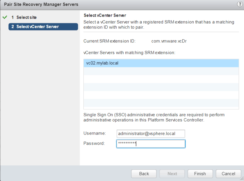
2. Provide remote site SSO administrative credentials. Click on Finish.
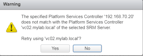
3. If get below warning, click on Yes
4. Now we see sites are paired now with green check mark.
Configuring inventory mappings
Next, as you can see from the guide page, we will configure inventory mappings.
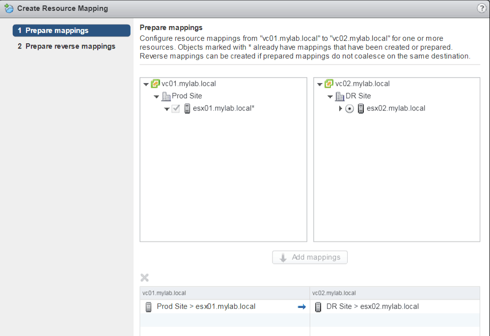
Create resource mappings
1. Click on create resource mappings
Basically, in our lab, we only have one ESX at each site, there is not much options here. ESX01 at Prod Site will map to ESX02 at DR site – that means VMs will move from ESX01 to ESX02 during Disaster Recovery or Migration by SRM.
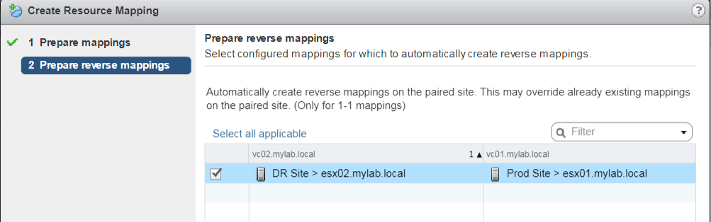
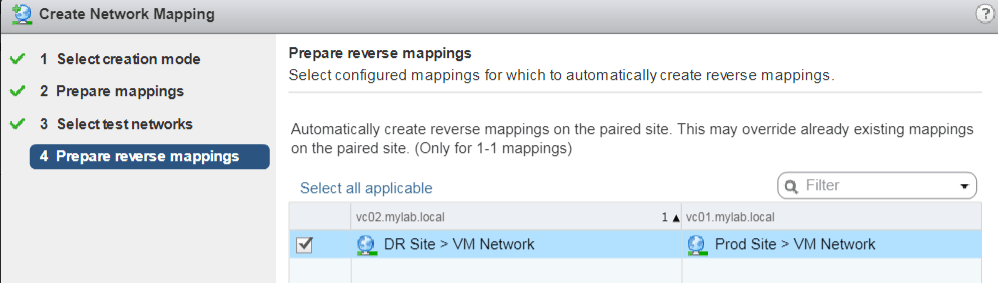
2. Configure reverse mapping
Reverse mapping will define the resource when failback from DR site to Prod Site.
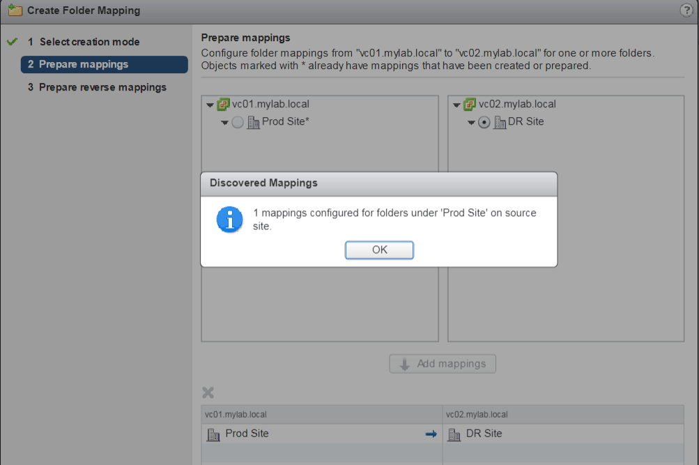
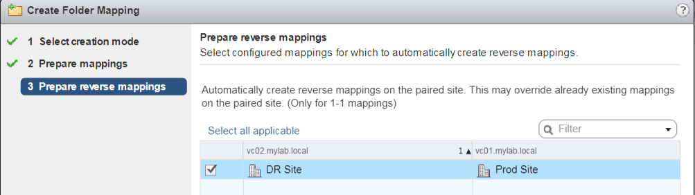
Create folder mappings
Some customer may group VMs into folders based on the applications of the VM or Department and Organization Unit. When failover to remote site, we want the VMs group in the similar way.
1. Click on Create folder mappings
2. Reverse mappings for folder
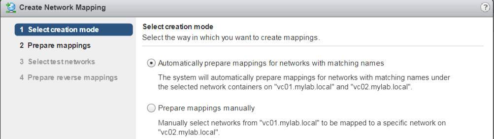
Create network mappings
Network at Prod site and DR site may totally different. In worst cases, server need change to a new IP address after server is up at DR site. That why we need configure network mappings correctly.
1. Either select automatically or manually for network mapping
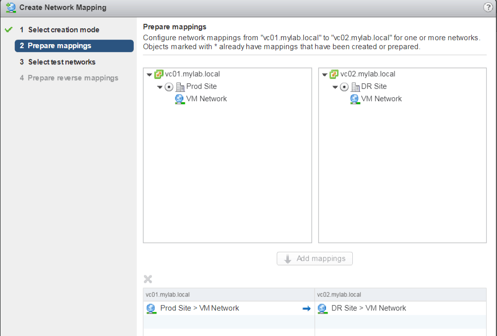
2. In our lab, we only have one network for VMs – “VM Network”
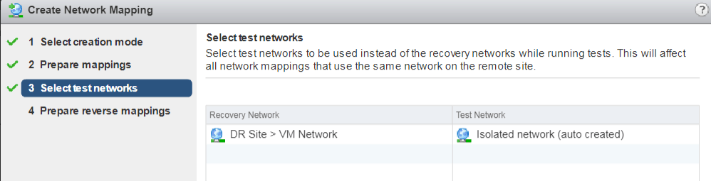
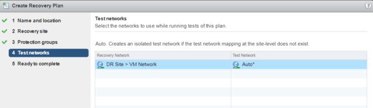
3. When we do test Recovery Plan, VMs will be powered on and connected to an isolated network – which will be created by SRM.
4. Configure reverse mappings for network
Configure placeholder datastore
SRM placeholder datastores is used to store the protected virtual machines at the recovery site. Placeholder datastores does not need to be replicated and it must be visible to all ESX hosts in the cluster. Since we only have one ESX host each site, we don’t need a shared lun. Just configure placeholder on the local datastore.
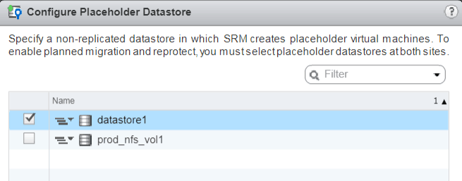
Please Note: placeholder datastore need to be configured at both sites – if re-protect will be configured from DR site to Prod site.
Configure array manager and enable array pair
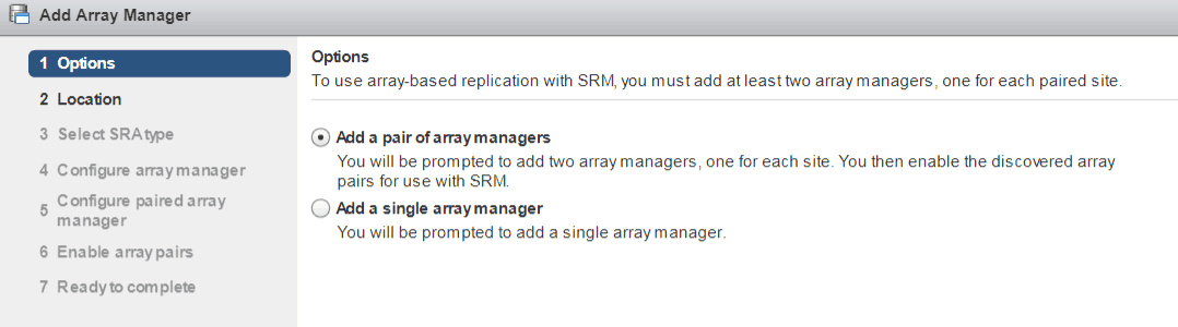
Now it comes the most import part for SRM – configure array manager
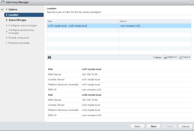
1. Click on Add Array Manager
2. Verify site information
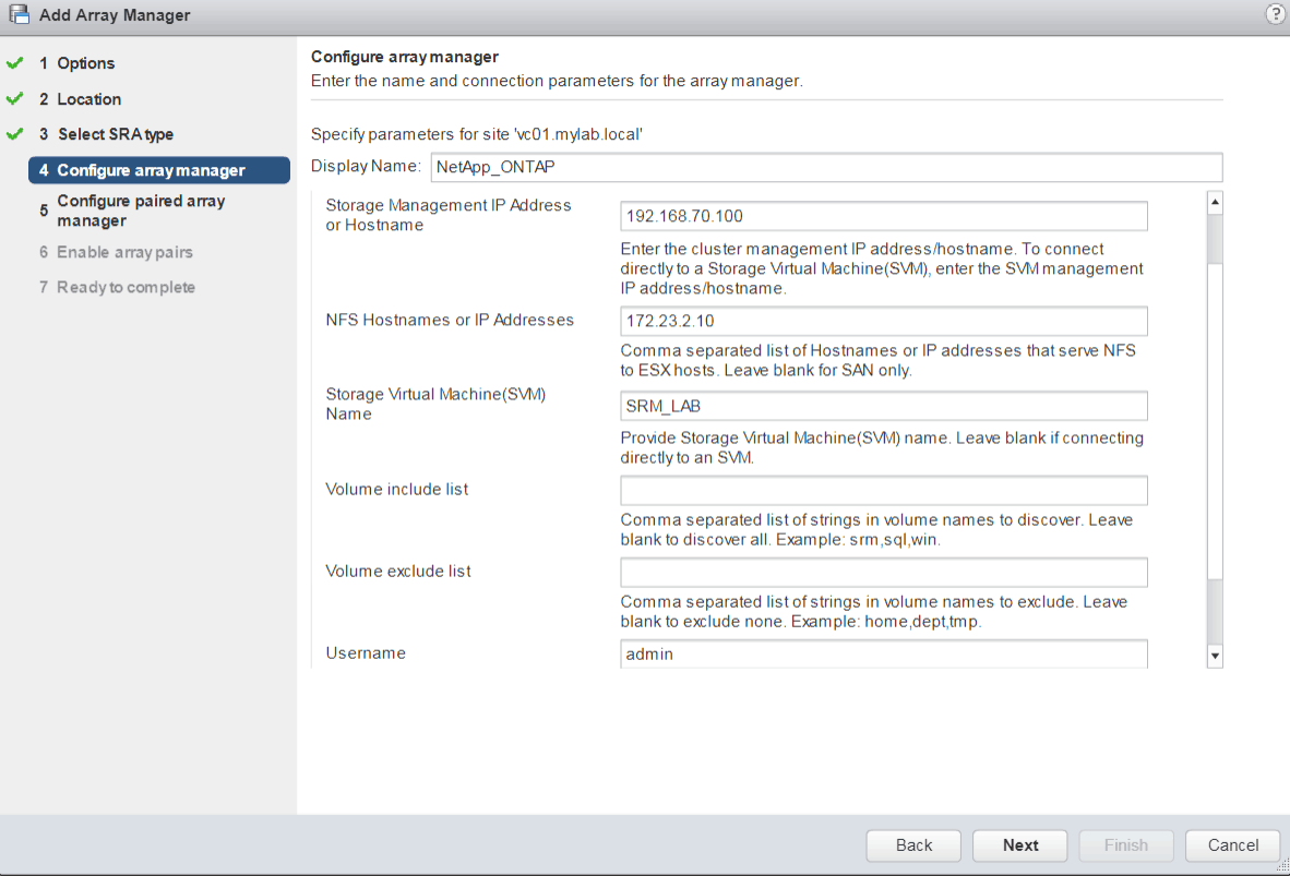
3. Verify SRA type

4. Enter array information and login credentials for Prod Site
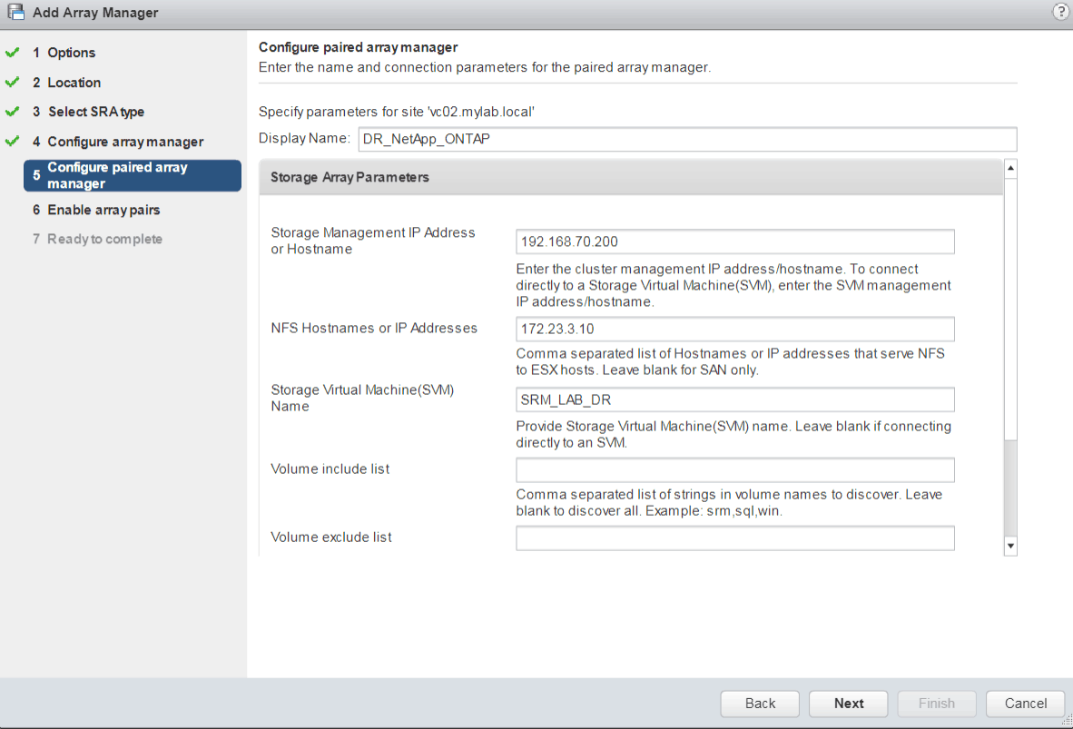
5. Enter array information and login credentials for DR Site
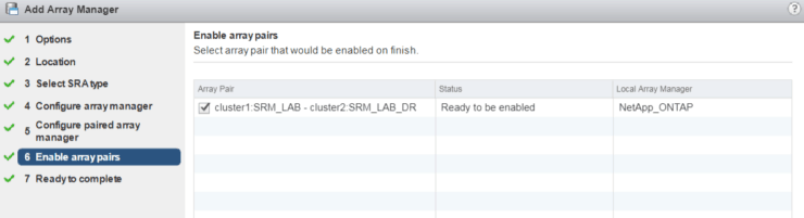
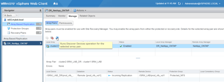
6. Enable array pairs
From below screenshot, we can see the cluster pairs and SVM pairs
7. Now if we go to Array Based Replication – we can see replication information on volume level.
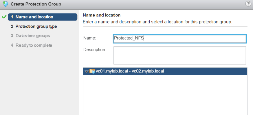
Create a protection group
1. Click on Create protection group
2. Specify protection group type

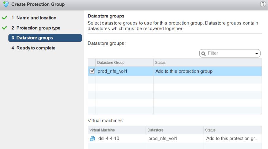
3. Selected Datastore Groups to be used for protection group (basically select the lun we enabled snapmirror data protection on NetApp array). It also lists all the VMs on those datastore groups.
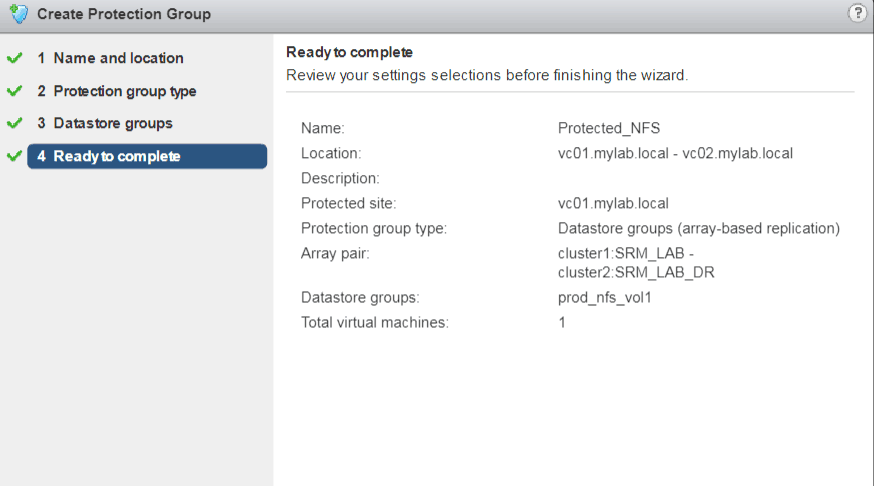
4. Review and Finish.
Create a recovery plan
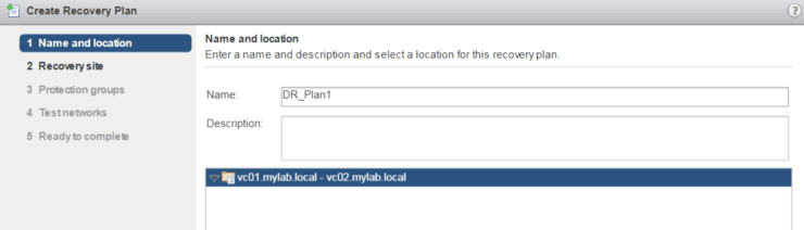
Finally, we’re ready to create one Recovery Plan
1. Put a name for recovery plan
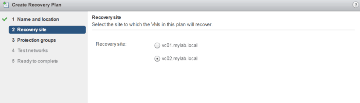
2. Select Recovery site
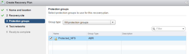
3. Select protection group for this plan
4. Select Test networks
5. Review and Finish
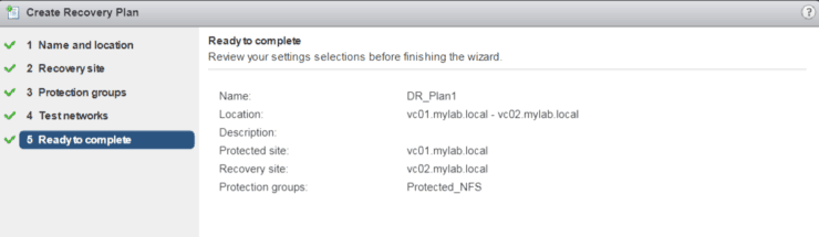
6. Now we have a Recovery Plan
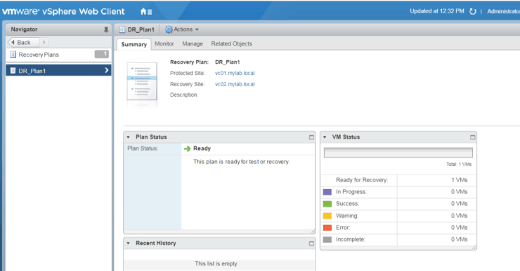
Test and Run Recovery Plan
After we create a Recovery Plan, we can test it or run it. The difference is that:
- During Test Recovery Plan, we will keep existing Snapmirror Data Protection – keep them in sync and we won’t break the mirror and use the replicated DR volume for testing. Instead, we take a snapshot of DR volume and present snapshot volume to ESX server at DR site. Also, during test Recovery Plan, VMs at DR site will be put on an isolated network.
- During Run Recovery Plan, we will suspend the snapmirror replication and make DR volume read/writable. Present DR volume directly to ESX server. SRM will power on VMs from DR volume Datastores and put VMs to respective networks based on network mappings.
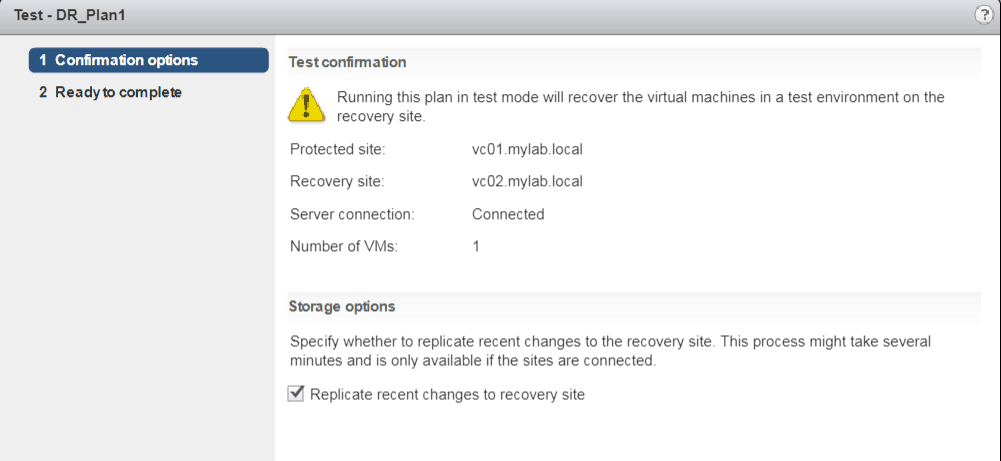
Test Recovery plan
1. Click on test button 

2. Review and select replicate recent changes to recovery site
3. Review and Complete.
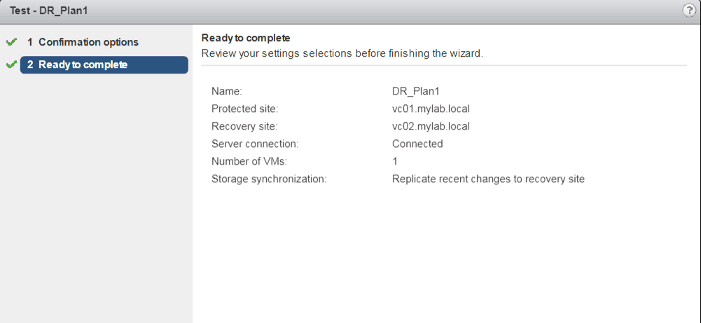
4. Monitor all the steps during Recovery Plan test
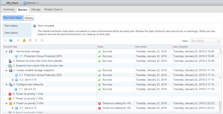
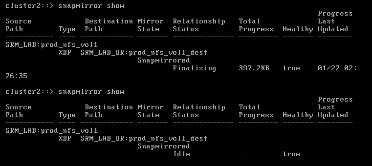
Also, at the same time, you can ssh to DR Site NetApp cluster2
Snapmirror state is SnapMirrored during test
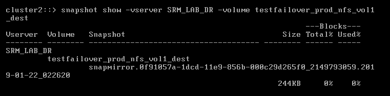
There is a new testfailover_xxx snapshot volume been created and presented to VM
Cleanup after Test Recovery Plan
Basically, cleanup will Power off VMs, delete the snapshot volume (testfailover_xxxxx) was used for testing and testing the temporary created isolated network.
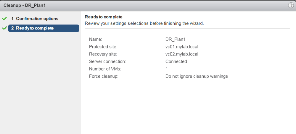
1. Actions Cleanup

2. Cleanup confirmation
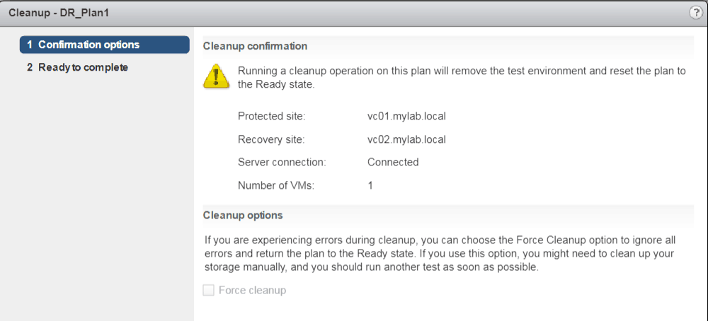
3. Finish
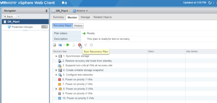
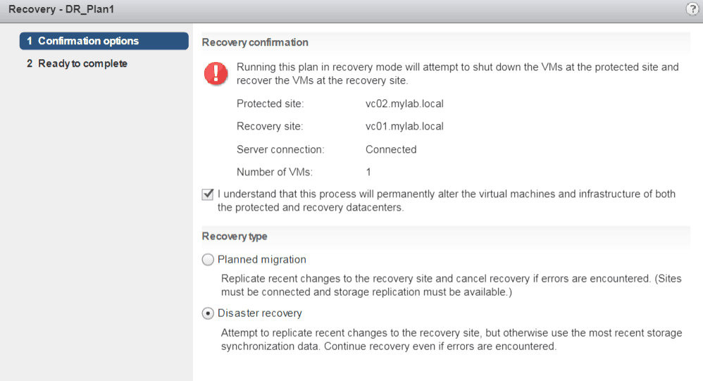
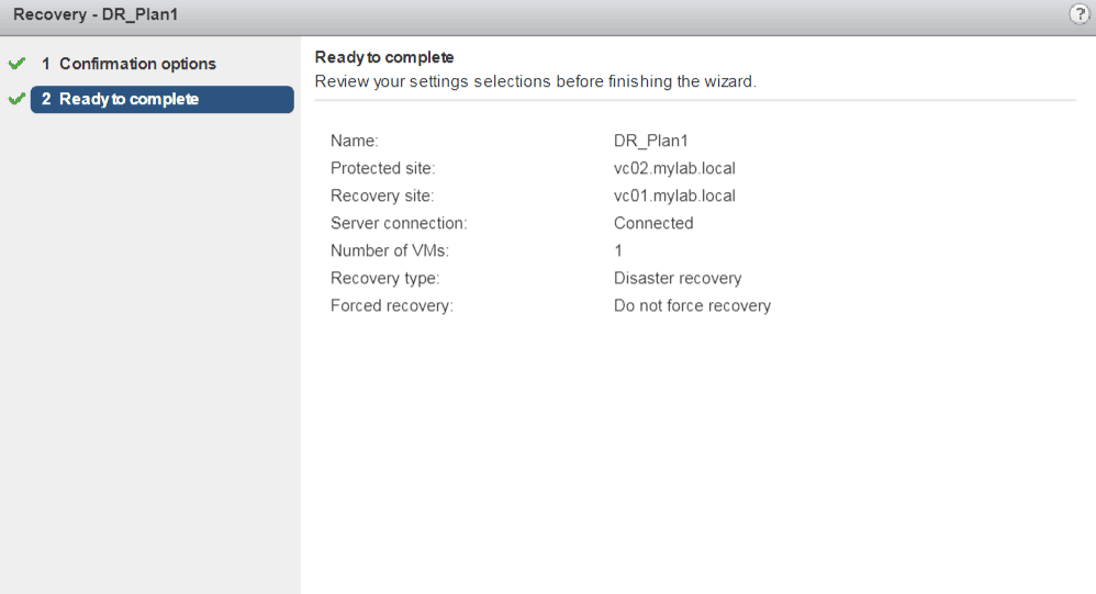
Run Recovery Plan (Prod Site failover to DR Site)
1. Click on Run button
2. Make sure you understand the risk
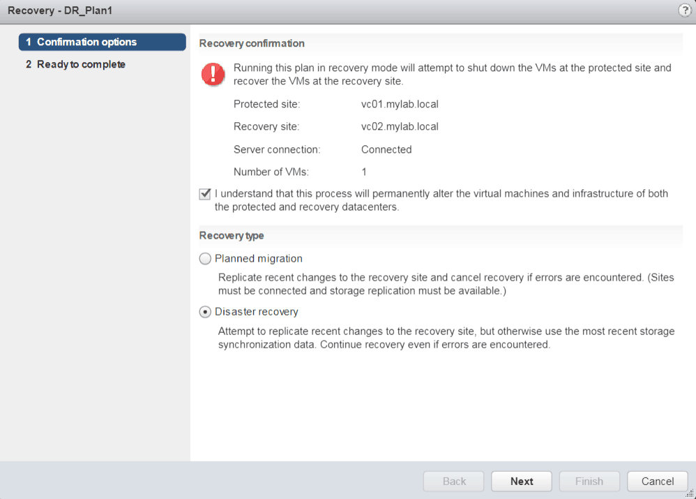
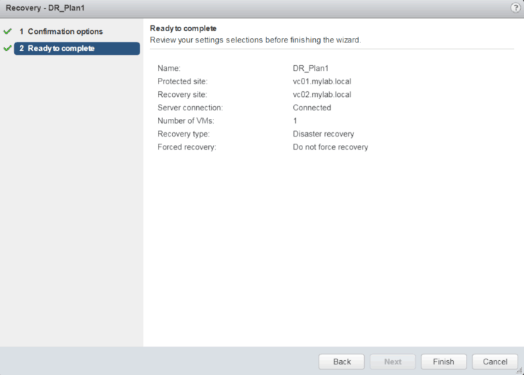
3. Finish
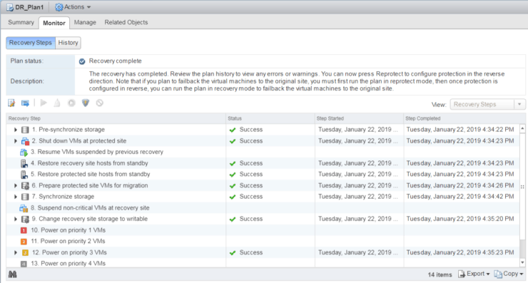
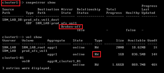
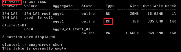
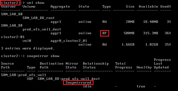
Use CLI to verify SnapMirror status and volume type changes
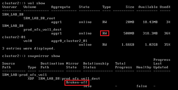
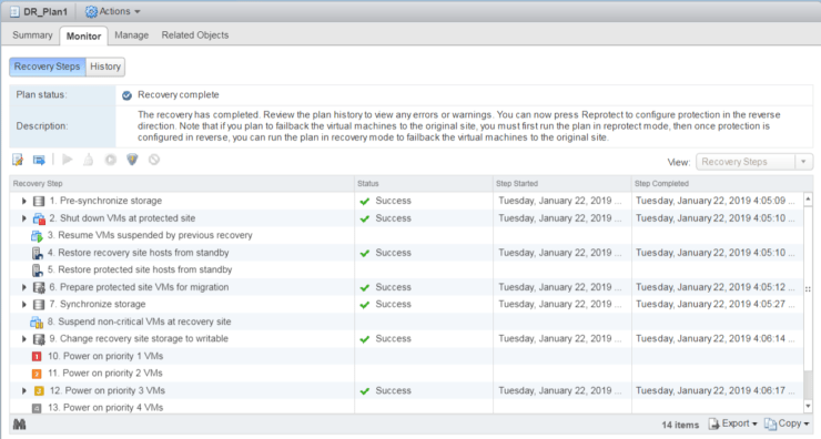
SRM Monitor tab
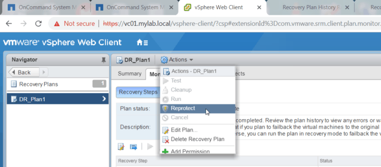
Reprotect (Sync from DR Site to Prod Site)
Now assume Prod Site is recovered and let’s re-protect from DR Site to Prod Site
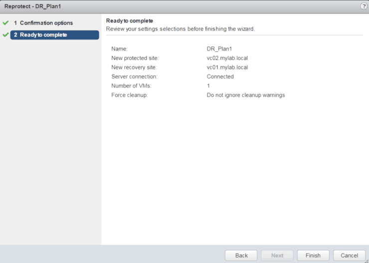
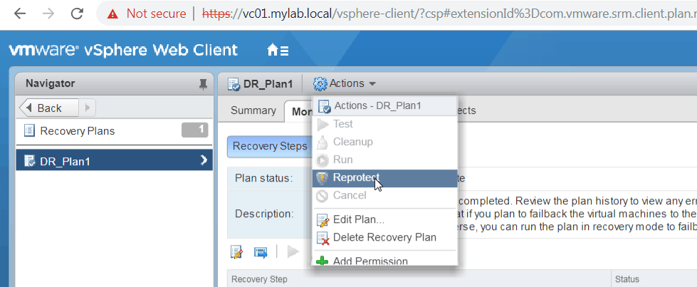
Click on Reprotect
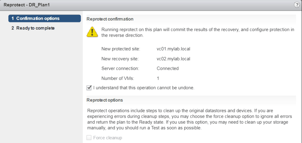
Per screenshot below, DR site will become the new protected site and Prod Site will become the new recovery site
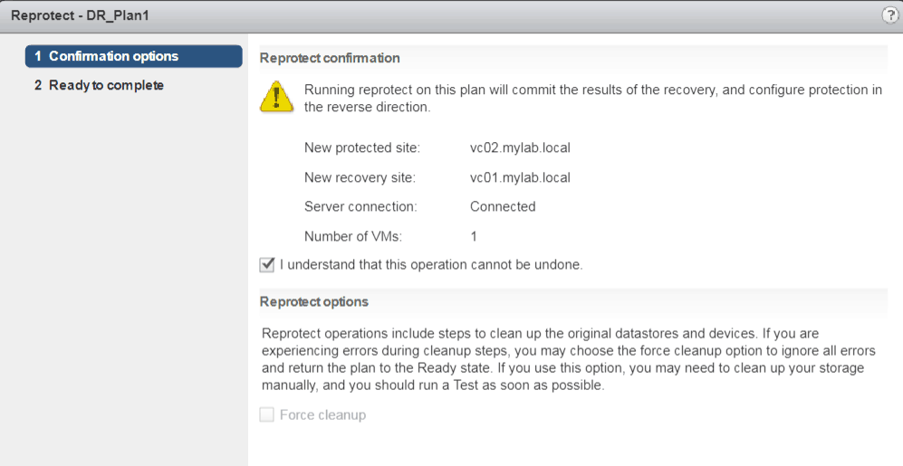
Finish
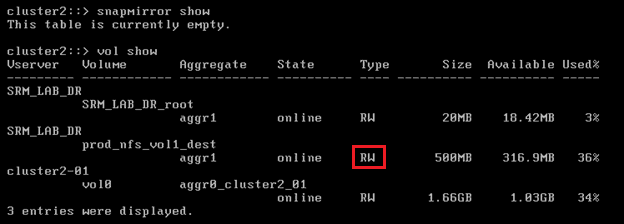
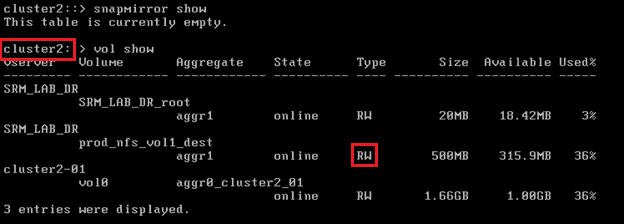
Again, use CLI on both Cluster1 and Cluster2 to verify
Clsuter1
Cluster2
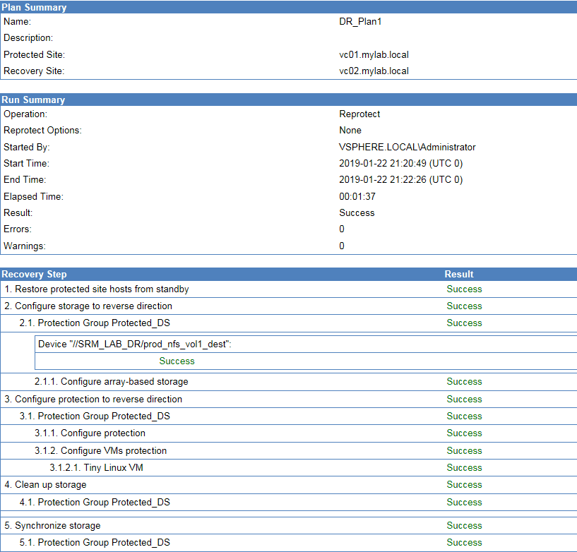
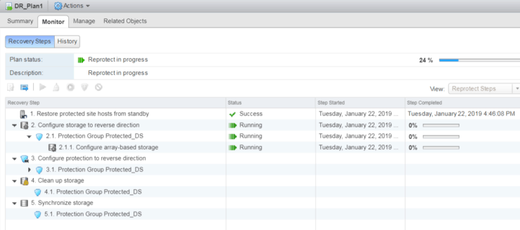
Also, you can go to Monitor History tab and generate a nice report.
Run Recovery Plan (DR Site failover to Prod Site)
Run Recovery Plan again – will failover from DR Site to Prod Site
Monitor all the steps from Monitor Recovery Steps tab
Use CLI to verify
Reportect (Sync from Prod Site to DR Site)
Finally, let run reprotect to recover everything back to normal replication direction: Prod Site DR Site

Using CLI
Click Here to get my 'NetApp ONTAP 9 Storage Complete' training course.