In this Cisco CCNA training tutorial, you’ll learn about manipulating the Spanning Tree Root Bridge Election. Scroll down for the video and also text tutorial.
The Spanning Tree Root Bridge Election on Cisco Switches Video Tutorial

Srinivasan Manohar

I took the CCNA exam yesterday and I passed it in the first attempt. It would not have been possible without taking your course.
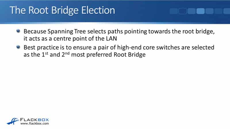
The Root Bridge Election
Since Spanning Tree selects paths pointing towards and away from the Root Bridge for forwarding traffic along, the Root Bridge acts as a center point of the LAN. Best practice is to ensure that a pair of high-end core switches are selected as the first and second most preferred Root Bridge.
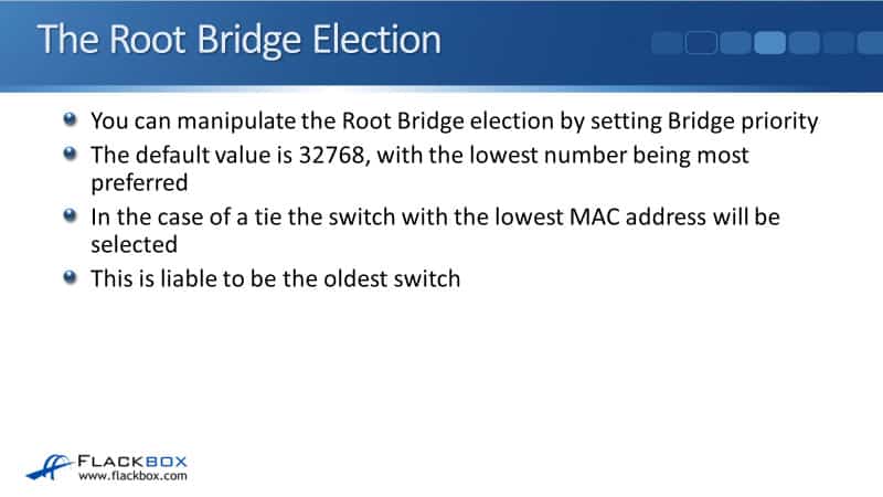
You can manipulate the Root Bridge Election by setting Bridge priority on your switches. The default value is 32768, and the lowest number is preferred. In the case of a tie, the switch with the lowest MAC address will be selected.
If you do not manually set the Bridge priority on your switches, they're all going to default to 32768. The switch with the lowest MAC address will be the Root Bridge and that is liable to be the oldest switch in your network.
Suboptimal Root Bridge
If you think about it, whenever Cisco makes a new switch, we're going to increment the MAC address. So, the lowest MAC address is probably going to be the oldest switch. That is likely to give you suboptimal Root Bridge selection.
In on our example below, all switches have been left with the default Bridge Priority. You'd be surprised at how often this does actually happen in production networks.
That is because Spanning Tree works just fine straight out of the box and on a lot of networks, therefore, administrators don't touch it at all. They just leave it as is and that can lead to the problem as you see in our example.
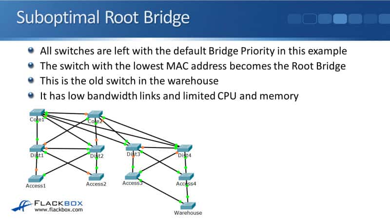
In the example, the switch with the lowest MAC address becomes the Root Bridge and that happens to be the old switch that we've got in the warehouse down in the bottom right.
That old warehouse switch has got little bandwidth links. It has fast Ethernet links compared to Gigabit Ethernet and it's old so it's got limited GPU and memory resources.
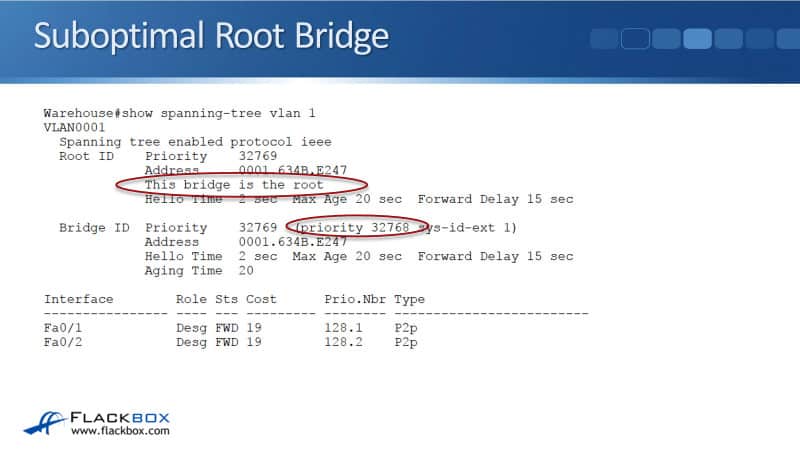
If we check this, I go on to the warehouse switch and enter the command:
show spanning-tree vlan 1
I can see here that this bridge is the root and the priority is the default of 32768.
Now, we'll look at the actual paths that traffic will take throughout our network. I've removed links that have got blocking ports on them in the diagram. It only shows the Spanning Tree where the traffic is going to be forwarded over.
Let's see what would happen if we had a PC that was connected into the Access1 switch on the left and it sent traffic to the Access3 switch over near the right-hand side.
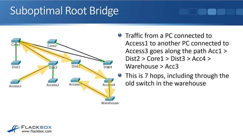
The PC connected to Access1 sends some traffic in with a destination address of the other PC. Access1 will extend it to Distribution2. It will then go at Core1, then to Distribution3, then Access4, then the Warehouse, and then Access3.
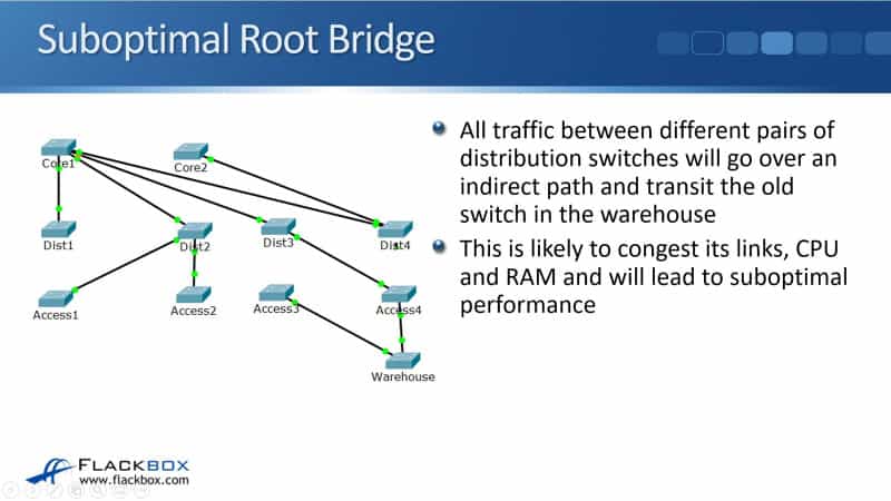
It's pinging around all over the network and going via the warehouse switch, and it's seven hops in total. That's the suboptimal Root Bridge selection. All traffic between different pairs of distribution switches will go over an indirect path and transit that old switch in the warehouse.
That's likely to congest some links overwhelmed with CPU and RAM, and of course, lead to suboptimal performance.
Root Bridge Primary Configuration
What we should have done was configure the Root Bridge to be sitting on one of our core switches so that all traffic is going to go through that path instead.
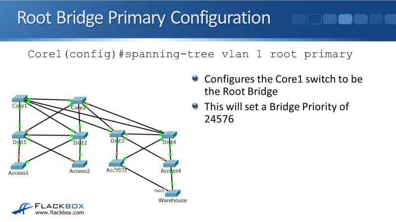
The way that you set this is that, at global config on the switch that you want to be the Root Bridge, enter the command:
spanning-tree vlan 1 root primary
Now, you can have different switches being the Root Bridge for different VLANs. Here, we're using VLAN 1 for our example. When you put that command, it sets a Bridge Priority of 24576 which is better than the default Bridge Priority. It is manipulating the elections so that this switch will be elected as the Root Bridge.
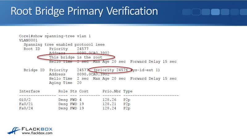
Root Bridge Primary Verification
To verify it, I go to Core1, enter the commands:
show spanning-tree vlan 1
It will show the message, "This bridge is the root," and I can see the priority is 24576.
Optimal Root Bridge
If we now look at the Spanning Tree in the diagram here, again, we've set the core bridge as the Root Bridge. I've taken out all of the links that have got blocking parts on there.

If we now send traffic from a PC connected into Access1, sending it to another PC if it's connected to Access3, the path it will go along is Access1 to Distribution2, to Core1, to Distribution4, to Access3.
Now, you see it's only five hops as compared to the seven hops that we had before. It's going along the most direct path which is going through the core. So, that is much more optimal Root Bridge placement.
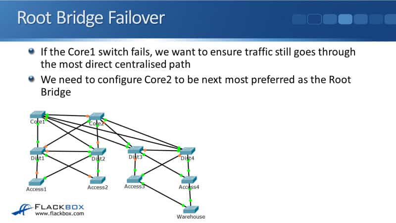
Root Bridge Failover
Using the same example, if the Core1 switch fails, we want to ensure that traffic still goes through the most direct centralised path.
To do that, we need to configure Core2 to be the next most preferred Root Bridge. If we didn't do that and Core1 went down, when we had that outage we would be back to the warehouse being the Root Bridge again and we want to avoid that. We always want traffic to be going through the core.
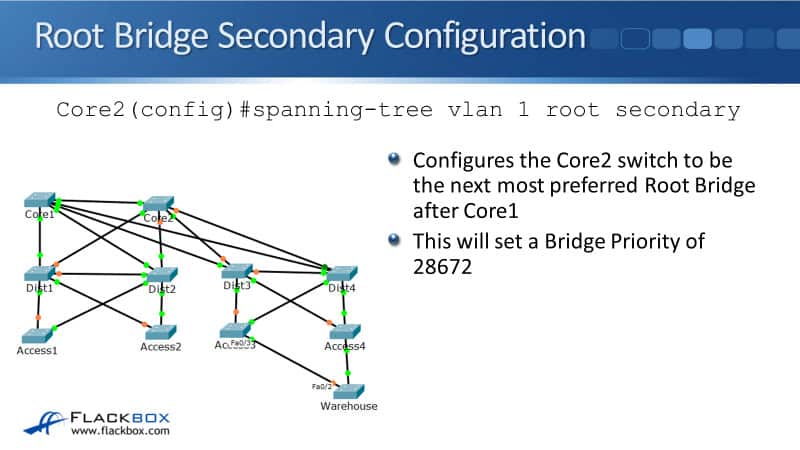
Root Bridge Secondary Configuration
To do that, we go on the command line on Core2, and we enter the command:
spanning-tree vlan 1 root secondary
It's root primary on the switch you want to be the Root Bridge and its root secondary on the switch that you want to be the backup. That sets a Bridge Priority of 28672.
Root Bridge Secondary Verification
In Core2, we verify it with the same command:
show spanning-tree vlan 1
Here, I can see the Root Bridge is still on Core1, and that this has got the next best priority so this will be the second most preferred switch.

The Spanning Tree Root Bridge Election on Cisco Switches Configuration Example
This configuration example is taken from my free ‘Cisco CCNA Lab Guide’ which includes over 350 pages of lab exercises and full instructions to set up the lab for free on your laptop.
Click here to download your free Cisco CCNA Lab Guide.
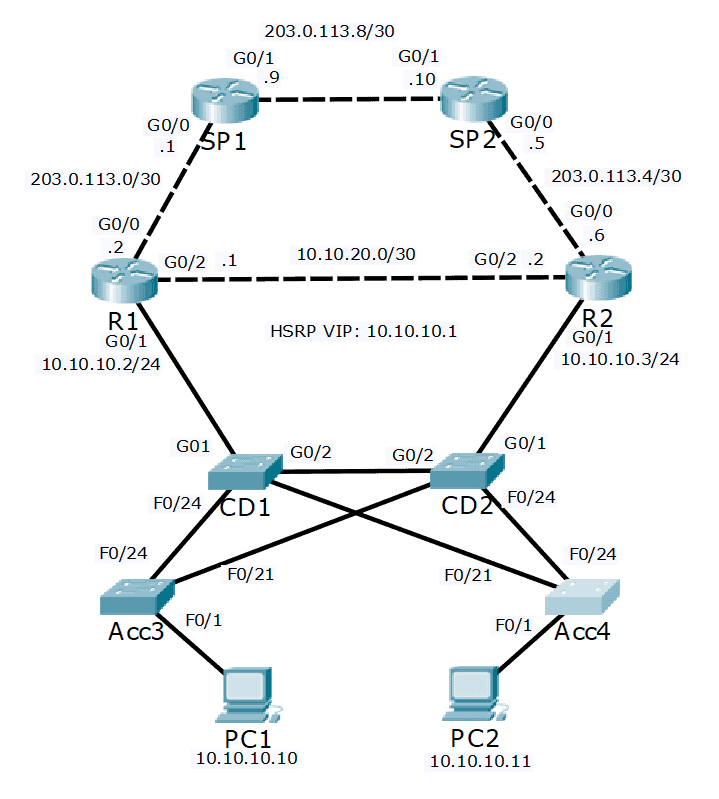
- Configure the network so that traffic between the PCs and the Internet travels along the shortest available path. If a core/distribution switch fails traffic should failover to the next shortest available path. Do not change any Layer 3 configuration such as HSRP settings.
We need to configure the Spanning Tree so it aligns with the HSRP configuration. R1 is the HSRP active gateway. R1 is directly connected to the core/distribution switch CD1 (but not CD2) so we should make this the Spanning Tree Root Bridge.
CD1(config)#spanning-tree vlan 10 root primary
2. If CD1 fails we need to ensure that the Spanning Tree Root Bridge will failover to CD2 rather than an access layer switch.
CD2(config)#spanning-tree vlan 10 root secondary
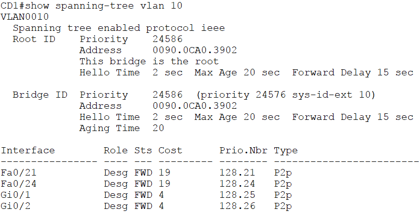
3. Verify CD1 has the best Bridge Priority and becomes the Root Bridge.
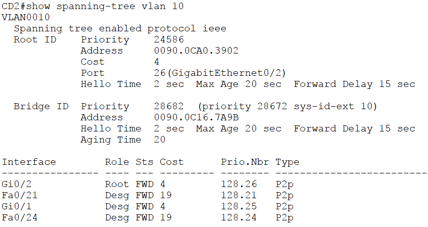
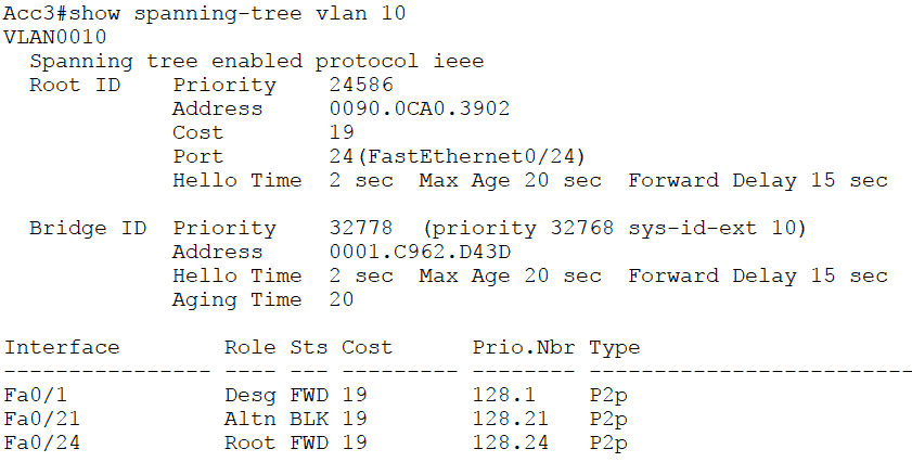
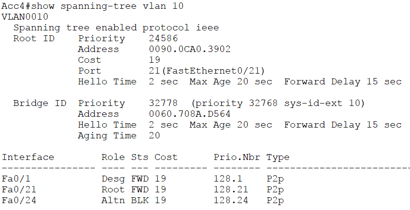
4. Check the other switches to verify CD2 has the next best Bridge Priority.
5. Verify the end to end traffic path between the PCs and the Internet by using the ‘show spanning-tree vlan 10’ and ‘show mac address-table’ commands as shown in the last lab exercise.
Additional Resources
Understanding and Configuring Spanning Tree Protocol (STP) on Catalyst Switches: https://www.cisco.com/c/en/us/support/docs/lan-switching/spanning-tree-protocol/5234-5.html
Spanning Tree Configuration: https://www.ciscopress.com/articles/article.asp?p=2832407&seqNum=6
What is a Root Bridge (Switch), Bridge (Switch) Priority Value and Bridge (Switch)ID: https://www.omnisecu.com/cisco-certified-network-associate-ccna/what-is-a-root-bridge-switch.php
Libby Teofilo

Text by Libby Teofilo, Technical Writer at www.flackbox.com
Libby’s passion for technology drives her to constantly learn and share her insights. When she’s not immersed in the tech world, she’s either lost in a good book with a cup of coffee or out exploring on her next adventure. Always curious, always inspired.