In this Cisco CCNA training tutorial, you’ll learn about how Spanning Tree works. Spanning Tree is an industry-standard protocol, which is enabled by default on all vendors’ switches. Scroll down for the video and also text tutorial.
How the Spanning Tree Works Video Tutorial
Lee Gaines

I have passed my CCNA with the help of your course, and landed a job as a network administrator at a local hospital for my first real IT job. I am so excited about getting started in this role. Thanks for all your help in helping me make huge strides in getting into this exciting new career path!
Broadcast storms can be devastating on a local area network. We need to avoid that at all costs and that is why we use Spanning Tree.
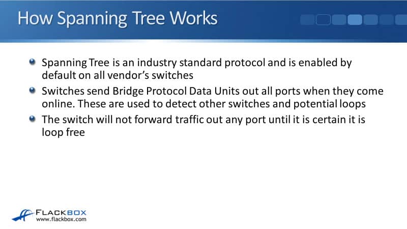
Switches send BPDUs, Bridge Protocol Data Units, when they come online. BPDUs are used to detect other switches and potential loops. The switch will not forward traffic out any port until it's certain that that port is loop free.
Spanning Tree Port States
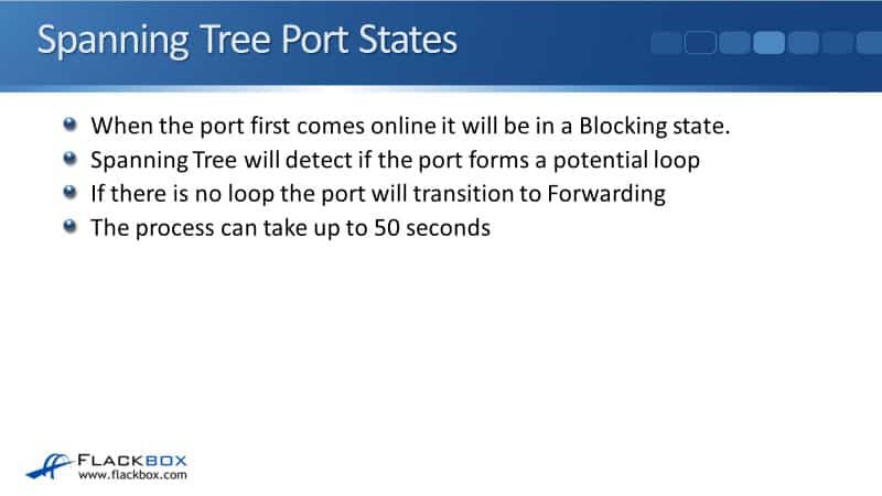
When the port first comes online, it will be in a Blocking state. The switch needs to make sure that it doesn't send traffic until it's sure that there's not a loop there.
Spanning Tree will detect if the port forms a potential loop, and if there's no loop, the port will then transition to a forwarding state. The process can take up to 50 seconds if you're using traditional legacy Spanning Tree.
The Bridge ID
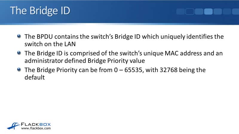
The BPDU contains the switches Bridge ID, which uniquely identifies the switch on the LAN. The Bridge ID is comprised of the switches MAC address and also an administrator defined Bridge Priority Value. The Bridge Priority can be from 0 to 65535, and 32768 is the default.
The Root Bridge
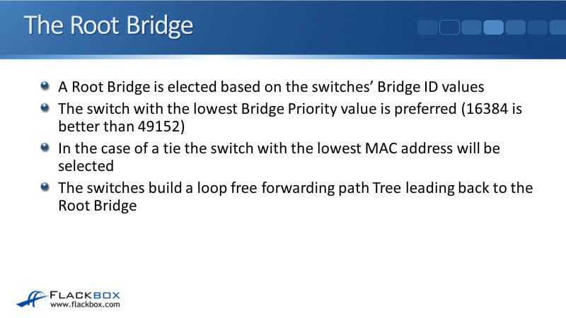
A Root Bridge is elected based on the switches' Bridge ID values. The switch with the lowest Bridge Priority value in the LAN is preferred to be the Root Bridge.
If a Bridge Priority value is 16384, that would be more preferred than 49152 because it's a lower number. In the case of a tie, the switch with the lowest MAC address will be selected.
If you don't manually manipulate the Bridge ID, all the switches in your LAN will have the same Bridge Priority, which will be 32768. The switches build a loop free forwarding path Tree, which leads back to the Bridge.
Spanning Tree Example
In our example here, we've not manually set Bridge Priority on any of our switches. We've got four switches; our Core Distribution switches, CD1 and CD2, and we've got Access layer switches, Acc3 and Acc4.
Our switches have the following MAC addresses:
- CD1 - 1.1.1
- CD2 - 2.2.2
- Acc3 - 3.3.3
- Acc4 - 4.4.4
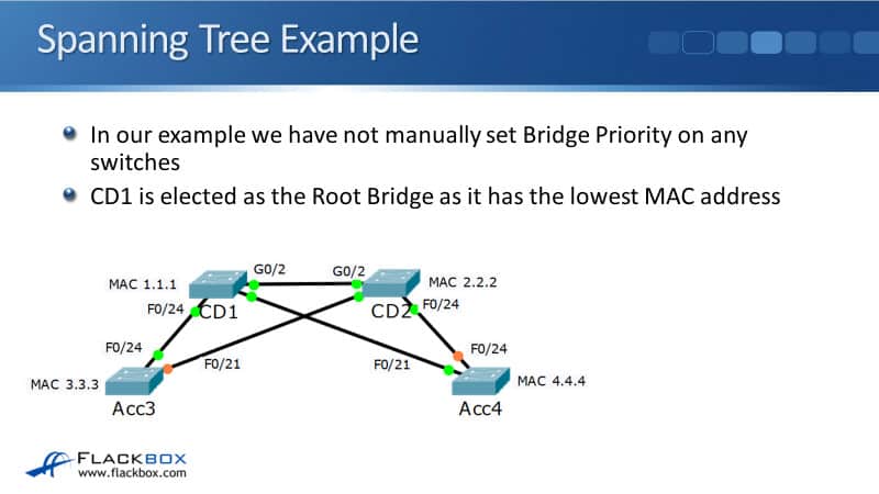
I haven't set a Bridge Priority on any of the switches, therefore, CD1 will be elected as the Root Bridge because it has the numerically lowest MAC address. The other switches will then detect the lowest cost path to get to the Root Bridge and those paths will transition to a forwarding state.
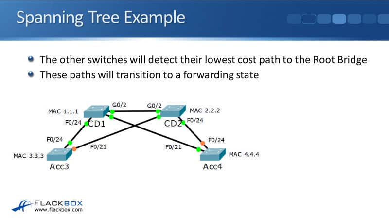
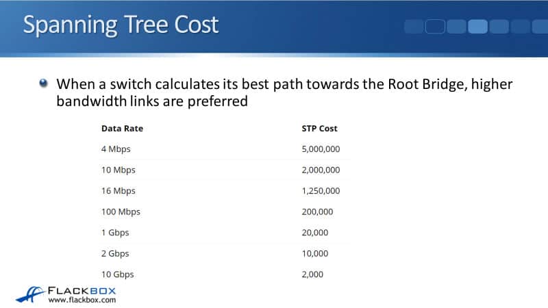
For the cost, when a switch calculates its best path towards the Root Bridge, higher bandwidth links are preferred. So, a gigabit ethernet interface would be preferred over a lower bandwidth fast ethernet interface, for example.
Root Ports
Each switches' exit interface on the lowest cost path towards the Root Bridge is selected as its Root Port. In our example, we already said that CD1 is the Root Bridge. From CD2's point of view, it's got three paths it can take to get to CD1:
- Via interface G0/2 that's directly connected to CD1
- Via Acc4, going out port F0/24 on CD2 and then out F0/21 on Acc4
- Via Acc3, going out port F0/21 on CD2 and then out Port F0/24 on Acc3
It's really obvious which is going to be the lowest cost path out of those three. It's going to the direct connection along the top on the G0/2 interface.
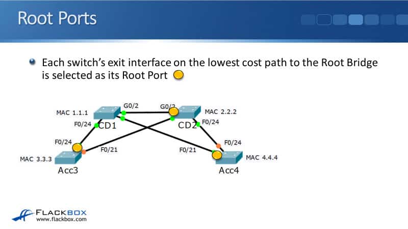
On CD2, interface G0/2 will be selected as its Root Port. Acc3 could get to the Root Bridge CD1, either out interface F0/24 directly, or it could go out interface F0/21 to CD2, and then across on interface G0/2.
Again, it should be obvious that a single fast ethernet link is going to be a lower cost than a gigabit ethernet plus a fast ethernet link. So Acc3 will select Port F0/24 as it's the lowest cost to get to CD1 and that interface becomes its Root Port.
Finally, we have Acc4 and it should be obvious again, which will be the Root Port on Acc4. It's going to be interface F0/21, which again is directly connected to the Root Bridge of CD1.
This is how the Spanning Tree operations work. The first thing that happens is a Root Bridge is elected, so all the switches come online and they send BPTU's to each other over the LAN. They all detect each other and whichever Bridge has got the best Bridge ID becomes the Root Bridge.
The next thing that happens is that all the switches in the LAN will figure out which is their Root Port. The best port to get towards the Root Bridge.
Load Balancing
Spanning Tree does not do load balancing. If a switch has multiple equal cost paths towards the Root Bridge, it will select the neighbour switch with the lowest Bridge ID, and that is going to be just one path.
In our example below, Core1 is the Root Bridge. Looking at it from Acc3 down to the bottoms point of view, it's got two equal cost paths it could take to get to the Root Bridge Core1.
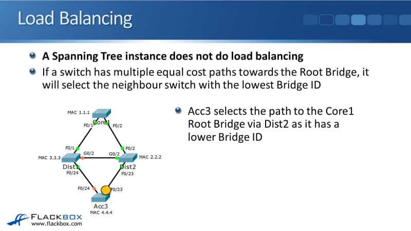
It could either go out interface F0/24 on the left hand side, or interface F0/23 on the right hand side. Spanning Tree is not a dynamic routing protocol. If this was a routing protocol, it would do equal cost to load balancing and traffic would go up both paths, but with Spanning Tree, it doesn't do load balancing.
It selects the one best path. So what happens here is, Acc3 selects the path to the Core1 Root Bridge via Dist2 as it has a lower Bridge ID.
Whenever there's a tie, the switch will select the neighbour switch with the lowest Bridge ID and that is Dist2 in this case. It's got a lower MAC address than Dist1 and we didn't set priority on either of them for this example.
If a switch has multiple equal cost paths via the same neighbour switch towards the Root Bridge, again, it will only select one of those paths. It will select the port with the lowest Port ID.
In our example here, we've actually got four uplinks towards the Root Bridge, Core1 from Acc3. We've got two going towards Dist1 and Dist2.
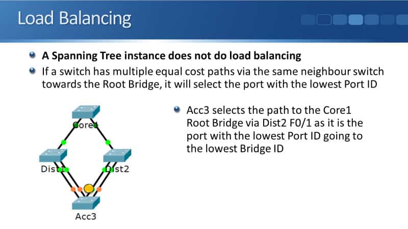
Out of those four uplinks, only one of them is going to be selected. Acc3 will select the path to the Core1 Root Bridge via Dist2 port F0/1 as it is the port with the lowest Port ID. It is going to the switch with the lowest Bridge ID.
Designated Ports
The first thing we select is the Root Bridge. Then, all of the other switches select their Root Ports towards the Root Bridge. The next thing is the Designated Ports.
Ports on the neighbour switch opposite the Root Port are Designated Ports. Your Root Ports point towards the Root Bridge, Designated Ports point away from it. All ports in the Root Bridge will always be Designated Ports because obviously they are going to be pointing away from the Root Bridge when they're on it.
In the example here, we already discovered which were our Root Ports. On the interface on the other side of those links, they will be set as Designated Ports. Looking at CD2, its Root Port was G0/2 along the top. The interface on the other side, G0/2 on CD1 will be set as a Designated Port.
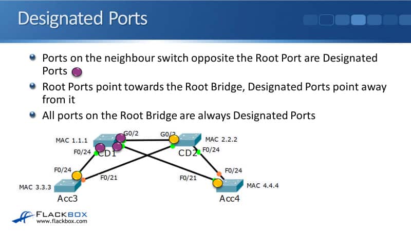
Acc3's Root Port was F0/24. The interface on the other side of that link is F0/24 on CD1, and finally, it should be obvious that Acc4's Root Port is F0/21. Therefore, the Designated Port will be on F0/21 on CD1. You can see here that all the ports on the Root Bridge are always Designated Ports.
Root Ports and Designated Ports Forward Traffic
You're maybe thinking, "Well, it's obvious which are the Designated Ports. It's just all of the ports that are on the Root Bridge," but that's not necessarily the case. In our example here, I'm going to add another switch into the network, which is then not directly connected to the Root Bridge. It's connected to CD2.
If you look at that switch, it should be pretty obvious that it's Root Port is going to be on the interface facing CD2. The Designated Port will be the port on CD2, which is facing back towards that Root Port.
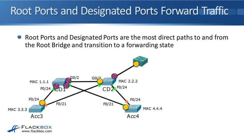
Whenever we've got a Root Port, the interface on the other side of the link is going to be a Designated Port. Your Root Ports and your Designated Ports are the most direct paths to and from the Root Bridge. The Root Bridge serves as a central point of the networking for where our traffic flows are going to go to and from.
Because your Root Ports and Designated Ports are on the most direct path, they're always going to transition to a forwarding state.
Other Links
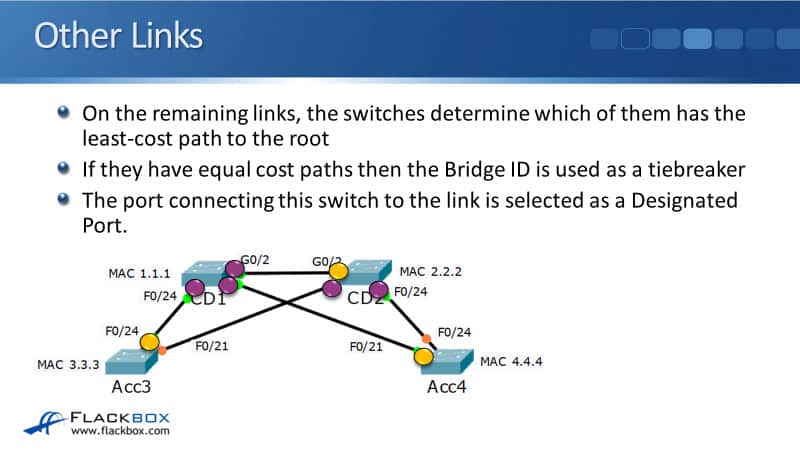
On the remaining links, the switches determine which of them has the least cost path to the Root. If they have equal cost paths, then the Bridge ID is used as a tie-breaker. The port connecting this switch to the link is selected as a Designated Port.
Blocking Ports
Looking at our diagram above, you see that we've got two links leftover which has not been configured with Root and Designated Ports. That's the link from interface F0/21 on Acc3 to F0/21 on CD2, and the other link is on Acc4 Port F0/24, going up to F0/24 on CD2.
On those two remaining links, they're links that would form a loop. So, we're going to need to block one side of the link and the other side of the link will remain a Designated Port.
The side which has got the switch with the least cost path to the Root or the lowest Bridge ID will be the Designated Port site. The other side will be the blocking Port.
Right now, CD2 has got a gigabit ethernet direct link going to the Root Bridge of CD2. That's going to be a lower cost than Acc3 and Acc4, which have got fast ethernet links. CD2 is going to be the preferred switch, so, it's going to have Designated Ports on each side of those links.
From Acc3 F0/21 to CD2 F0/21, the CD2 side is going to be the Designated Port. It's also going to be the CD2 side which is the Designated Port going on the link on F0/24 down to Acc4.
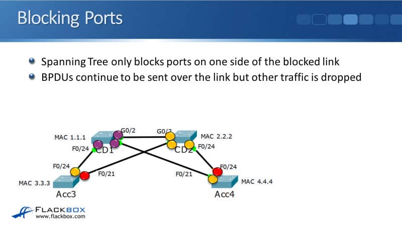
Any ports which have not been selected as a Root Port or a Designated Port pair would potentially form a loop, and those are going to be selected as our Blocking Ports. In our diagram right now, we've only got two Ports left over, that's F0/21 on Acc3 and F0/24 on Acc4.
If those ports were also forwarding, we would be forwarding everywhere and we would have a loop, so we're going to block on those ports to break the loops. We block on F0/24 on Acc4 and on F0/21 on Acc3.

Now, you can see that I've completed my diagram. Every single port has been labeled as either a Root Port, a Designated Port, or a Blocking Port.
Spanning Tree only blocks Ports on one side of the blocked link. BPDUs continue to be sent over the link, but other traffic is dropped. We continue to send BPDUs so that Spanning Tree can detect if any links go down and failover to a different path around that.
Root, Designated, and Blocking Ports
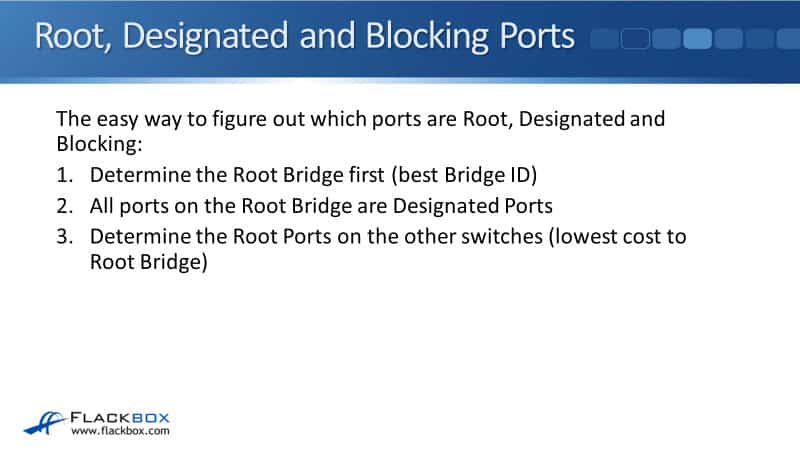
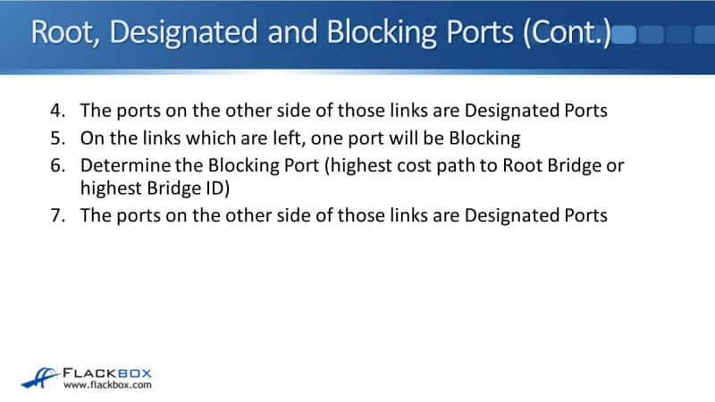
I'll summarise here about the quick and easy way to figure out the Root, Designated, and Blocking Ports which really aligns with how Spanning Tree actually works as well.
Layer 2 Forwarding Paths
This is the entire network of our example. These are the available paths through the network and if you look at the switching part, you can see that I've removed the links which were blocked. All traffic on the network can only go over those links.
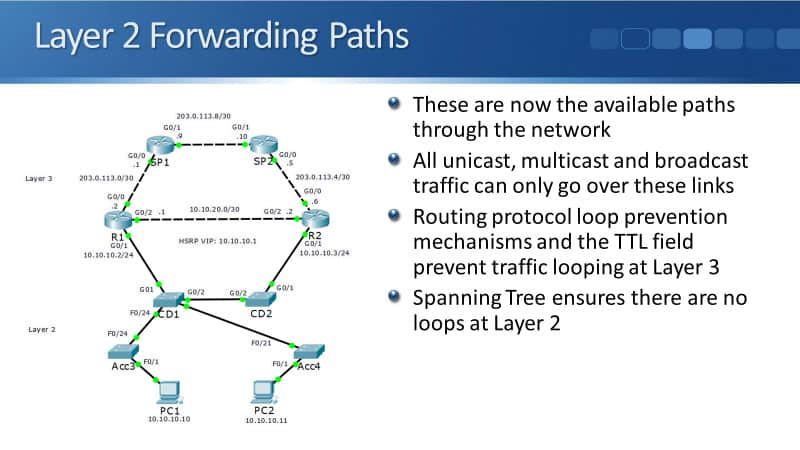
If you look up at the top paths of a network, you see that there are loops between our routers. Routing protocol loop prevention mechanisms on the TTL field in our IP header prevent traffic from looping at layer three.
Looking at the switched part of the network, you see that there are no actual loops there now. They've all been removed by Spanning Tree, so Spanning Tree ensures that there are no loops at layer two.
Ethernet Path Selection Review
When PC1 sent out an ARP request for its default gateway at R1, you can see that now we are using Spanning Tree. The traffic still gets flooded everywhere over the Tree, but it doesn't get moved anywhere.

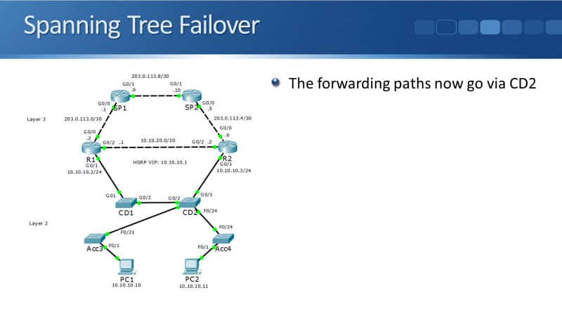
Spanning Tree Failover
Traffic can still get where it needs to go, but we're not going to have any broadcast storms formed by loops. If an uplink to CD1 fails, Spanning Tree will detect it and transition the redundant link to forwarding.
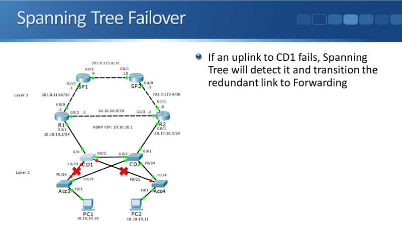
You can see in the example here that my uplink from Acc3 to CD1, and my uplink from Acc4 to the Root Bridge CD1, both failed. If that happens, Spanning Tree will detect it and it will fail it over to the next best path, still ensuring that there are loops.
So this is what our topology would look like if we had lost those uplinks to CD1. You can now see that we still have just that one Spanning Tree again, with no loops in it. Now the traffic is going via CD2.
Additional Resources
Configuring Spanning Tree: https://www.cisco.com/c/en/us/td/docs/switches/lan/catalyst4500/12-2/15-02SG/configuration/guide/config/spantree.html
Cisco CCNA – Spanning Tree Protocol(Root Bridge, Root/Designated/Blocked Ports): https://www.certificationkits.com/cisco-certification/ccna-articles/cisco-ccna-switching/cisco-ccna-spanning-tree-protocolroot-bridge-rootdesignatedblocked-ports/#:~:text=A%20Root%20Bridge%20is%20a,elected%20as%20the%20Root%20Bridge.
Cisco Spanning Tree Protocol Guide (STP Examples and Configuration): https://www.networkstraining.com/cisco-spanning-tree-protocol/
Libby Teofilo

Text by Libby Teofilo, Technical Writer at www.flackbox.com
Libby’s passion for technology drives her to constantly learn and share her insights. When she’s not immersed in the tech world, she’s either lost in a good book with a cup of coffee or out exploring on her next adventure. Always curious, always inspired.