In this Cisco CCNA training tutorial, you’ll learn how to align your spanning tree and HSRP configuration so that they line up with each other. Scroll down for the video and also text tutorials.
Spanning Tree and HSRP Alignment Video Tutorial

Corey Thomas

I just wanted to say thank you. You have by far been the best instructor ever for the CCNA. Your labs, videos, note cards, subnetting practice, and AlphaPrep recommendation has helped me pass the CCNA in exactly 6 weeks by following your study plan.
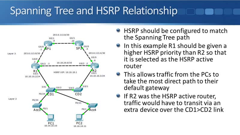
Spanning Tree and HSRP Relationship
In the diagram below, I've already configured my core distribution switches, CD1 and CD2, to be my root primary and secondary for the root bridge. CD1 is currently the root bridge and I've got blocking links going from Acc3 to CD2 and from Acc4 to CD2.
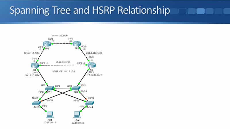
At layer two, the traffic going North and South bound is going via CD1 right now. I want my HSRP configuration to match the spanning tree path. So, R1 should be given a higher HSRP priority than R2. R1 is selected as the HSRP active router and it allows traffic from the PCs to take the most direct path to their default gateway.
If R2 was the HSRP active router, traffic would have to transit via an extra device over the CD1 to CD2 link. Right now, CD1 is the root bridge and I'm going to configure R1 as the HSRP active gateway.
If traffic goes from PC1 up to the internet, it goes via Acc 3, CD1, and then R1. If traffic's coming from PC2, it goes from PC2 to Acc4 to CD1, and then R1. If R2 was my HSRP active gateway, traffic from PC1 would go to Acc3, then CD1, CD2, and R2.
It’s going to take an extra hop over my core distribution switches. You would want to line up your HSRP on your spanning tree configuration so that traffic is going to go over the most direct path, at layer two with spanning tree, and at layer three with HSRP as well.
Aligned ‘Active/Active’ HSRP & Spanning Tree
Finally, let's look at an example of how we could do load balancing with aligned HSRP and spanning tree configuration. Going back to the topology diagram, PC1 got IP address 10.10.10.10 and it's in VLAN 10. PC2 is in VLAN 10 as well.
Imagine that PC2 is in VLAN 20 and it's got the IP address, 10.10.20.10. With the configuration, I'm going to configure it so that traffic for VLAN 10 PC1 is going to go up through the path via CD1 and R1, and traffic from PC2 and VLAN 20 is going to go up via the path, via CD2 and R2.
I'm splitting half my traffic is going to go along the left side path. Half of my traffic is going to go along the right side path. I get load balancing this way, rather than all traffic going up one path.
Also, if one path failed, the traffic will failover to going over on the other side of the path. I'm not going to have any outages if I have any single point of failure. So how do we do the configuration?
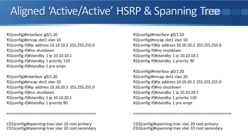
R1 is going to be the HSRP active for VLAN 1. I'm using router on a stick sort of interfaces here. So, the commands on R1 would be:
interface gig 0/1.10
encap dot1q vlan 10
ip address 10.10.10.2 255.255.255.0
no shutdown
standby 1 ip 10.10.10.1
standby 1 priority 110
standby 1 preempt
On R2, we’ll have the commands:
interface gig 0/1.10
encap dot1q vlan 10
ip address 10.10.10.3 255.255.255.0
no shutdown
standby 1 ip 10.10.10.1
standby 1 priority 90
On core distribution switch, CD1, I set spanning tree VLAN 10 root primary and spanning tree VLAN 20 root secondary with the commands:
spanning-tree vlan 10 root primary
spanning-tree vlan 20 root secondary
R1 will be selected as the active HSRP gateway for VLAN 10 and CD1 will be selected as a root bridge with spanning tree.
In the diagram, all traffic for VLAN 10 is going to go up and down the left path via CD1 and R1. For VLAN 20, on R2, we enter the following configuration:
interface gig 0/1.20
encap dot1q vlan 20
ip address 10.10.20.3 255.255.255.0
no shutdown
standby 1 ip 10.10.20.1
standby 1 priority 110
standby 1 preempt
For R1, we’ll use the following commands:
interface gig 0/1.20
encap dot1q vlan 20
ip address 10.10.20.2 255.255.255.0
no shutdown
standby 1 ip 10.10.20.1
standby 1 priority 90
R2 will be the HSRP active gateway for VLAN 20 using IP address 10.10.20.1. I also want to configure a spanning tree. I want this traffic to go through CD2. On CD2, the configuration would be:
spanning tree vlan 10 root secondary
spanning-tree vlan 20 root primary
That's how you do your configuration. You line up HSRP and spanning tree so that you get load balancing and automatic failover as well.
Additional Resources
Understanding and Troubleshooting HSRP Problems in Catalyst Switch Networks: https://www.cisco.com/c/en/us/support/docs/ip/hot-standby-router-protocol-hsrp/10583-62.html
HSRP (Hot Standby Routing Protocol): https://networklessons.com/cisco/ccie-routing-switching/hsrp-hot-standby-routing-protocol
Chapter: Configuring HSRP: https://www.cisco.com/c/en/us/td/docs/switches/lan/catalyst3560/software/release/12-2_52_se/configuration/guide/3560scg/swhsrp.html
Libby Teofilo

Text by Libby Teofilo, Technical Writer at www.flackbox.com
Libby’s passion for technology drives her to constantly learn and share her insights. When she’s not immersed in the tech world, she’s either lost in a good book with a cup of coffee or out exploring on her next adventure. Always curious, always inspired.