
In this NetApp training tutorial, I will cover NetApp SnapMirror Data Protection Mirrors, which I gave a shorter overview of in this post. Scroll down for the video and also text tutorial.
NetApp SnapMirror Data Protection DP Mirrors Video Tutorial

Lance Candia

Concise detailed information. Neil is not vague about his explanation. He provides some “what if’s” as well as “for instances” which again take out any ambiguity pertaining to the training. He stays on point, doesn’t go off topic or on a tangent. He keeps it relevant with some historical or legacy information where it makes sense. Overall I would use the word to sum up this training as “impressive”.
NetApp SnapMirror Data Protection DP Mirrors
Data Protection mirrors can replicate a source volume to a destination volume in the same or in a different cluster. Typically we'll be replicating to a different cluster. They can be used for the following reasons:
- To replicate data between volumes in different clusters for disaster recovery. This is usually the main reason we use DP mirrors. When used for disaster recovery, intervention is required to failover to the DR site.
- To provide load balancing for read access across different sites.
- Data migration between clusters.
- To replicate data between different SVMs in the same cluster.
- To replicate data to a centralised tape backup location.
When we talk about ‘NetApp SnapMirror’ in general, we're talking about DP mirrors.
Disaster Recovery
The first reason mentioned, and the best-known reason for implementing Data Protection mirrors is for disaster recovery.
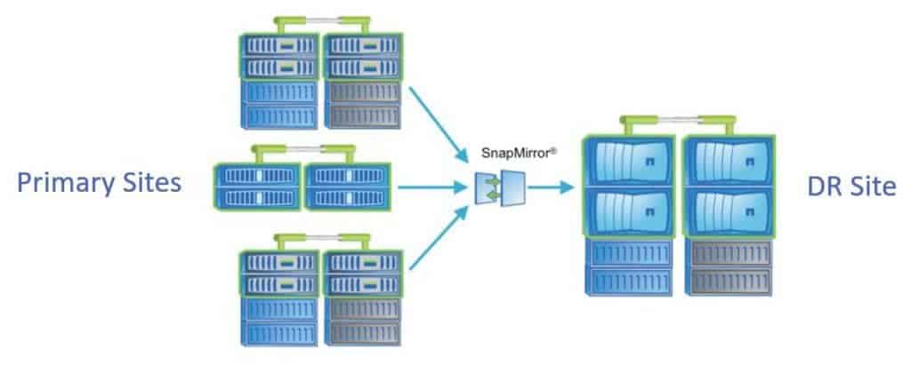
Let’s say we have a main site that we're using as the active site for our data, and we also have a standby disaster recovery site. We're going to use DP mirrors to replicate from the source site to our destination, the DR site.
In this scenario, we could use inexpensive SATA drives in the DR site and SSDs or SAS drives in the primary site. To save money we can use less expensive drives in the DR site because it's just being used as a hot spare.
Deciding on the types of disks to use will need to be a management decision though. The reason being if you do have to failover and the DR site is running SATA disks, you're going to have a performance hit until you can get your primary site running again. If you want to be able to maintain the same performance during a disaster, then you will have to use the same disk types in both sites.
Read-Only Load Balancing
The next reason to use NetApp SnapMirror DP mirrors is for read-only load balancing. A read-only load balancing setup consists of a writable copy at the source site and read-only copies in the destination remote sites.
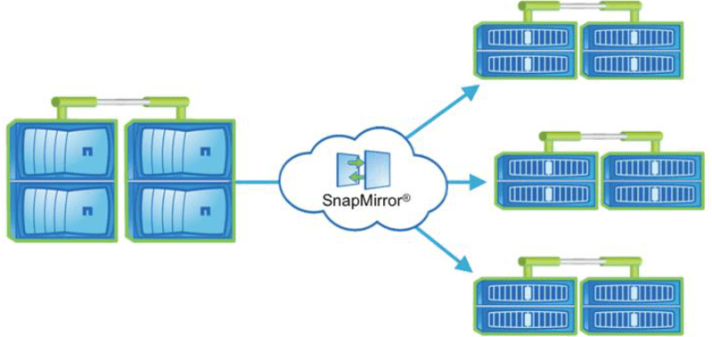
In this configuration, let's say that our main site is in Singapore and we've got another site in Kuala Lumpur. The Singapore site is the writable copy and KL is the read-only copy. Let's say we've also got a read-only copy in Sydney. What we can do is direct the users who are based in Southeast Asia to the Singapore or KL sites and the users who are based in Australia to the Sydney site.
We're going to give them the lowest latency access based on where they're accessing the data from. Not only does this give us a disaster recovery solution, because we've got the data in more than one site, but it also gives us load balancing for our read-only data. It's kind of like building your own content delivery network.
Data Migration
Another reason we can use SnapMirror Data Protection mirrors is for data migration. If we had some data that was in Singapore and we wanted to move it across to Sydney, we could use a DP mirror.
Staging to Remote Tape
The final reason that we're going to cover is for staging to remote tape. In the example here, we've got multiple remote systems. We’re replicating them all into a central site where my tape devices are also located so I can back them up there.
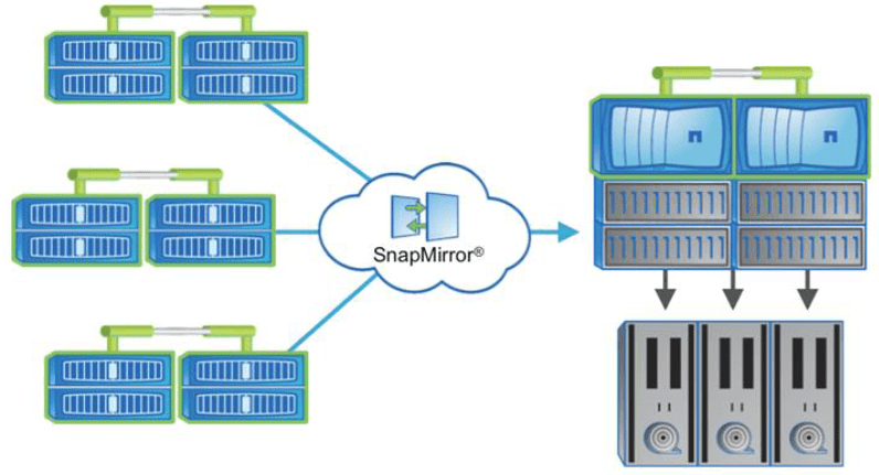
This saves me having to buy and manage tape devices in each of my sites.
Initial Configuration Steps on Both Clusters
To configure, we need to run through the initial configuration steps.
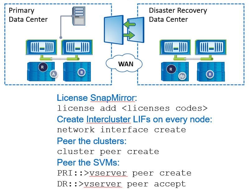
Use the ‘license add’ command to license SnapMirror on both clusters. Then, we also need to configure Intercluster and logical interfaces on every node in both clusters. After we've done that, we can then peer the clusters. We also need to peer the SVMs.
Create and Initialise NetApp SnapMirror Volume Mirror Relationship
Next, we're ready to create and initialise the volume mirror relationship. These commands are all done on the DR site.
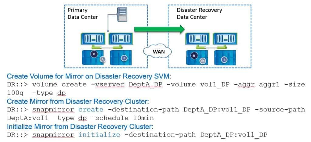
After we've created an SVM we need to create a volume to replicate the data into. The command for this is ‘volume create’. Here we’ve named the VServer on the destination side ‘DeptA_DP’. We create a volume called ‘vol1_DP’ that we're going to use to replicate volume 1 from the source site. We've put it in aggr1 with a size of 100 gigabytes.
When you create the destination volume, it needs to be at least as big as the source volume. Then we use the ‘-type dp’ switch. This says that it's going to be used as the destination for a SnapMirror relationship, which turns it into a read-only volume.
Next, we create the mirror relationship. The command for this is ‘snapmirror create’. The destination path in our example here is ‘DeptA_DP:vol1_DP’. The source path is ‘DeptA:vol1’. We say ‘-type dp’ for a Data Protection mirror.
We configure the schedule here as well. In our example, we are using a 10-minute schedule. When we put the ‘snapmirror create’ command in, it creates the relationship but it doesn't actually replicate any data across yet. We need to do that next.
To do that, we use the ‘snapmirror initialize’ command. We can specify just the destination path. I don't need to put in the source path as well because we can only replicate one volume into the destination - when I specify the destination path, the system knows which replication I'm referring to. Once we do this, it will do the initial baseline transfer into our destination volume. That initial baseline transfer is going to be done over the network.
Tape Seeding
Incremental updates of snapshot copies from the source to the destination are feasible over a low bandwidth network connection. However, if we have a lot of data in our source volume and we're trying to send it out over a low bandwidth connection, that initial baseline replication could take a long time.
Alternatively, we can perform a local backup of the source volume to tape, then physically ship that tape over to the destination site. The mirror baseline initialization is then performed by restoring from the tape at the destination cluster. This saves us having to do it over the network. Tape seeding is supported for both SnapMirror DP mirrors and for SnapVault.
Failover
Okay, so at this point, we've got our SnapMirror relationship set up and we're replicating data based on our schedule. Let's say that after we've done this we do actually have a disaster. We lose the primary data centre and we want to failover to the DR site.
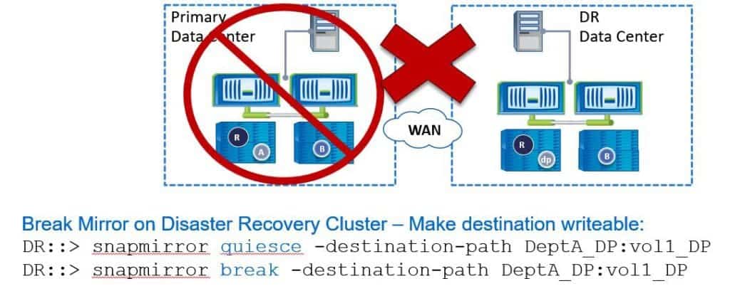
To do that, again, all the commands are always done on the destination site. In the DR site, the first command we enter is ‘snapmirror quiesce’, and then specify the destination path. What the ‘quiesce’ does is allow any replication that's currently running to complete, but it disables any future transfers.
Next, we do a ‘snapmirror break’ to break the SnapMirror relationship. Doing this will turn the destination site into a writable copy. If we do this while the primary site is still actually online, we want to take the source volume offline at the primary site to stop anybody making any changes there because the DR site is now writable. We don't want people making changes to both sides because then we'll get inconsistent copies of the data - they're not going to be the same.
You're now going to need to redirect the clients to point to the DR site. It's going to be on different IP addresses so you're going to need to direct them there. There are various tools you can use for this, such as GSLB (Global Server Load Balancing). This is not a Netapp solution. It comes from network vendors like Cisco and F5.
Mirror Configuration Steps on Destination Cluster
As well as directing clients over, there are other settings that you must take care of as well because although SnapMirror replicates the data (including file level permissions) to the destination volume, it doesn't replicate the ONTAP settings.
To failover to the DR site, as well as doing the SnapMirror commands, you’ll also have to make the destination volume accessible to your clients. You'll need to mount it into the namespace. You'll need to create CIFS shares and permissions if it's using CIFS, NFS export policies if it's using NFS, and your LUNs will need to be mapped to the correct igroups after failover if you're using SAN protocols.
Those tasks are all mandatory for the clients to be able to access and use the data. Other things that you should do are assign snapshot schedules and storage efficiency policies. You can perform those tasks before the disaster to save time if you have to do a failover. The final step you would perform would be the client redirection to the new destination.
Recovery Scenario A – Test Recovery
The next thing that we're going to cover in our scenario is a test recovery. We’re going to do a test failover but we didn't have an actual disaster. We perform the failover with the SnapMirror commands in the previous diagram.
We then write some test data into the DR site and checked that everything works. Once we've completed the test and it's been successful, we can then failback to the primary data centre.
To do that we use the command ‘snapmirror resync’ and specify the destination path. Again, this is done on the DR site. When using this command, any new data that was written to the destination (to the DR site) after the break is going to be deleted - it's going to be overwritten with what was on the primary data centre prior to that initial break. Only do this if you don't care about losing that data.
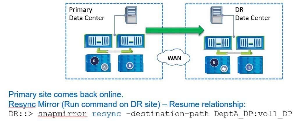
For example, you were testing DR and you just wrote some test information into the DR volume that you don't actually need to keep, or if you actually did have a disaster and the destination volume was just used for dev/test and you don't care about actually retaining any changes made to that volume while you were failed over to the DR site.
Recovery Scenario B – Restore Changes to Recovered Site – Part 1
The next recovery scenario to cover is if you do need to restore changes to the recovered site. This is where we’ve actually had a real disaster at a primary data centre and we failed over to our DR site.
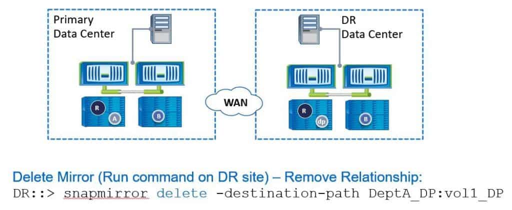
Let’s say the primary data centre was down for a week. During that week, we've been making changes to our volumes in the DR data centre and we now want to failback to the primary data centre when it’s online again. We’ll need to replicate the changes during that week from the DR data centre back to the primary data centre. To do this, we need to reverse the direction of the SnapMirror relationship.
The first thing we do is run the ‘snapmirror delete’ command with the destination path. Again, all these commands are configured on the destination side, so this is on the DR site.
Recovery Scenario B – Restore Changes to Recovered Site – Part 2
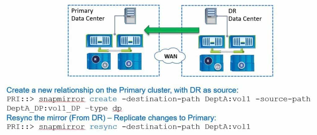
Now we're ready to reverse the direction of the SnapMirror relationship, so we're going to create a new relationship on our primary cluster with the DR as the source. Our commands are always done on the destination side. The primary data centre is going to be the new destination now, so these commands are done on the primary data centre.
First, we run ‘snapmirror create’. The destination path is now going to be ‘DetpA:vol1’. The source path is going to be ‘DeptA_DP:vol1_DP’ and we add ‘-type dp’ again. Then, if we were doing the initial setup, the next command would be ‘snapmirror initialise’ to do the initial baseline transfer. We don't need to do that here because we've still got the snapshots on the primary and the DR site so we can use those to just replicate the incremental changes across.
To do that, again on the primary site, we run the command ‘snapmirror resync’ and specify the destination path. This will now replicate the changes that happened in the DR site over the previous week back over to the primary data centre. We don't need to do a complete baseline transfer again. When that is done, we now have the current copy of the data in the primary data centre.
Recovery Scenario B – Restore Changes to Recovered Site – Part 3
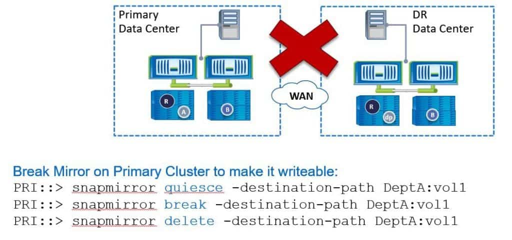
Our problem now is that the disaster recovery site is still a writable copy and it is replicating to the primary site which is read-only. We want it to be the other way around -we want the primary data centre to be the writable copy again. To do that, we need to once again break the SnapMirror relationship.
On the primary data centre (because it's currently the destination), we run a ‘snapmirror quiesce’, a ‘snapmirror break’ and then a ‘snapmirror delete’.
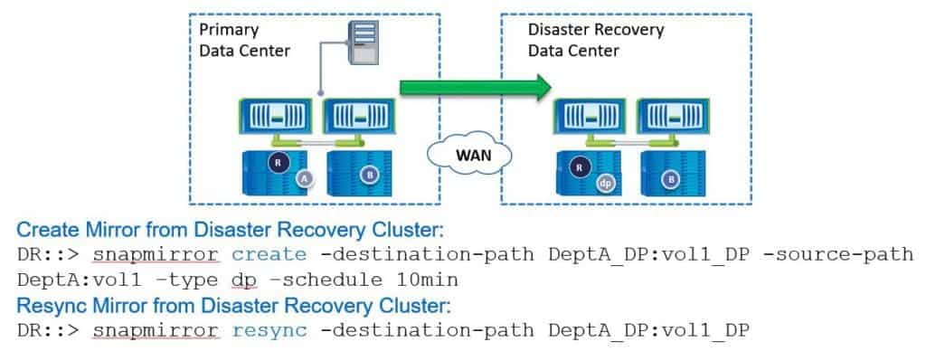
Then, back on the DR site, we're going to reverse the direction again so we’re running from the primary to the DR site.
On the DR site, we run ‘snapmirror create’. The destination path is going to be on the DR site now, so that's ‘DeptA_DP:vol1_DP’. The source path is at our main site, so that's ‘DeptA:vol1’. The type is DP, and we're going to configure a schedule of 10 minutes again.
Next, we need to resynchronize the relationship. We don't need to do an initialise because we've still got the snapshots there, so we can just do the incremental changes. The command is ‘snapmirror resync’ again. Once we've done that, we're back to how we started. The primary data centre is the writable copy and we're replicating it to the disaster recovery site which is the read-only copy.
Recovery Scenario C – Original Volume is Corrupted or Destroyed
The last recovery scenario to cover is if the original volume is corrupted or destroyed. Let’s say we had a disaster at the primary data centre, such as a fire, and we've actually lost all our hardware. In that case, we're not going to be able to do a resynchronize because we've lost the disks and therefore the snapshots. We're going to have to reinitialize the baseline.
The order of operations would be to get your replacement storage system in the primary data centre, do all the initial configuration on it, and then create a new volume there. Then, create a new relationship with the disaster recovery site as the source and initialise the mirror. We're going to have to do a new baseline transfer here, and then reverse the SnapMirror direction once it’s completed to make the primary data centre the writable copy again.
SnapMirror for SVM
The last item to cover on this topic is SnapMirror for SVM. SnapMirror for SVM creates a mirror copy of the data volumes and the configuration details of a source SVM on a destination cluster. This is an improvement of our normal data protection mirrors which just replicate the data and the permissions across.
As we covered earlier, if you do want to failover to your DR site, you will have to configure all the Netapp settings on your DR site before clients can access their data. When we use SnapMirror for SVM, this is taken care of for us. With SnapMirror for SVM you protect the SVMs identity and namespace, not just the data volumes.
The setup is quick and simple, and storage at the secondary SVM is provisioned automatically. Any configuration changes you make after the initial setup will be automatically replicated to the secondary SVM.
SnapMirror for SVM – Identity Preserve Mode
There are a couple of different ways we can implement SnapMirror for SVM. The first one is the ‘identity-preserve’ mode. When your primary and secondary SVMs are on the same extended layer 2 network (for example if you've got dark fibre between the sites or a layer 2 MPLS VPN), then you should configure SnapMirror for SVM to use ‘identity-preserve’ mode.
Both SVMs will use the same network services like DNS and Active Directory. If there's a need to failover to the DR site, the secondary SVM assumes all the configuration characteristics of the primary SVM, including the IP addresses of the LIFs. This is going to be very convenient - you don't need to reconfigure anything on the destination side.
You also don’t need to reconfigure your clients because they're still pointing at the same IP addresses. When you do a failover, the secondary SVM will effectively assume the primary SVM's identity. Both SVMs use the same CIFS server machine account as well.
Obviously, if the second SVM is going to assume the primary SVM's identity (including its IP addresses), this is an active/standby solution. We couldn't have them both active at the same time because we would have conflicting configurations.
SnapMirror for SVM – Identity Discard Mode
The other way we can configure SnapMirror for SVM is ‘identity discard’ mode. When your primary and secondary SVMs are on different IP subnets, configure them to use ‘identity discard’ mode.
Here, the primary and secondary SVMs use different network services, such as DNS and Active Directory. The primary SVM's data and namespace are still replicated to the secondary SVM, but only partial configuration data is preserved.
We're not going to copy everything across, such as IP addresses. This will require some reconfiguration when you need to do a failover. Clients access the preserved data through different network paths when you do a failover.
NetApp SnapMirror Data Protection DP Mirrors Configuration Example
This configuration example is an excerpt from my ‘NetApp ONTAP 9 Complete’ course. Full configuration examples using both the CLI and System Manager GUI are available in the course.
Want to practice this configuration for free on your lapthttps://www.flackbox.com/netapp-training-courseop? Download your free step-by-step guide ‘How to Build a NetApp ONTAP Lab for Free’

- Edit the virtual machine settings for the C2N1 virtual machine in VMware. Network Adapter 4 and Network Adapter 5 are currently in VMnet3. Change this to VMnet2 (the same as on the C1N1 and C1N2 virtual machines). This will place the e0d and e0e interfaces for the nodes in both clusters in the same Layer 2 network.
Open the virtual machine settings for C2N1.

Network Adapter 4 and Network Adapter 5 are currently in VMnet 3.

Change this to VMnet2.

- Ensure Cluster1 and Cluster2 both have the same date and time.
cluster1::> cluster date show
Node Date Time zone
--------- ------------------------- -------------------------
cluster1-01
7/6/2019 00:43:04 -07:00 US/Pacific
cluster1-02
7/6/2019 00:43:04 -07:00 US/Pacific
2 entries were displayed.
cluster2::> cluster date show
Node Date Time zone
--------- ------------------------- -------------------------
cluster2-01
7/6/2019 00:43:10 -07:00 US/Pacific
- Create two 100 MB volumes in the NAS SVM in Cluster1 named vol2 and vol3. Mount them in the namespace directly under the root volume.
cluster1::> volume create -vserver NAS -volume vol2 -aggregate aggr1_C1N2 -size 100mb -junction-path /vol2
Warning: The export-policy "default" has no rules in it. The volume will therefore be inaccessible over NFS and CIFS protocol.
Do you want to continue? {y|n}: y
[Job 84] Job succeeded: Successful
Notice: Volume vol2 now has a mount point from volume svm_root. The load sharing (LS) mirrors of volume svm_root will be updated according to the SnapMirror schedule in place for volume svm_root. Volume vol2 will not be visible in the global namespace until the LS mirrors of volume svm_root have been updated.
cluster1::> volume create -vserver NAS -volume vol3 -aggregate aggr1_C1N2 -size 100mb -junction-path /vol3
Warning: The export-policy "default" has no rules in it. The volume will therefore be inaccessible over NFS and CIFS protocol.
Do you want to continue? {y|n}: y
[Job 86] Job succeeded: Successful
Notice: Volume vol3 now has a mount point from volume svm_root. The load sharing (LS) mirrors of volume svm_root will be updated according to the SnapMirror schedule in place for volume svm_root. Volume vol3 will not be visible in the global namespace until the LS mirrors of volume svm_root have been updated.
- Update the NAS SVM root volume Load Sharing mirrors.
cluster1::> snapmirror update-ls-set -source-path NAS:svm_root
[Job 88] Job is queued: snapmirror update-ls-set for source "cluster1://NAS/svm_root".
- Share the volumes using vol2 and vol3 as the share names.
cluster1::> vserver cifs share create -vserver NAS -share-name vol2 -path /vol2
cluster1::> vserver cifs share create -vserver NAS -share-name vol3 -path /vol3
- Create a SnapMirror for SVM relationship to replicate the NAS SVM in Cluster1, to a new SVM named NAS_DR in Cluster2.
The NAS_DR SVM should keep the same CIFS machine account in the flackboxA.lab Active Directory domain and IP addresses as the NAS SVM.
Exclude vol3 in the NAS SVM from replication.
Use the ‘MirrorAllSnapshots’ policy. Replication should take place once every minute.
Use the ‘snapmirror create’ command if performing the configuration using the CLI.
Cluster peering and the 1min schedule are already configured.
Check which schedules exist on the source cluster.
cluster1::> job schedule cron show
Cluster Name Description
------------- ----------- -----------------------------------------------------
cluster1
1min @:00,:01,:02,:03,:04,:05,:06,:07,:08,:09,:10,:11,:12,:13,:14,:15,:16,:17,:18,:19,:20,:21,:22,:23,:24,:25,:26,:27,:28,:29,:30,:31,:32,:33,:34,:35,:36,:37,:38,:39,:40,:41,:42,:43,:44,:45,:46,:47,:48,:49,:50,:51,:52,:53,:54,:55,:56,:57,:58,:59
2min @:00,:02,:04,:06,:08,:10,:12,:14,:16,:18,:20,:22,:24,:26,:28,:30,:32,:34,:36,:38,:40,:42,:44,:46,:48,:50,:52,:54,:56,:58
5min @:00,:05,:10,:15,:20,:25,:30,:35,:40,:45,:50,:55
8hour @2:15,10:15,18:15
daily @0:10
hourly @:05
monthly 1@0:20
pg-15-minutely
@:10,:25,:40,:55
pg-6-hourly @3:03,9:03,15:03,21:03
pg-daily @0:10
pg-hourly @:07
pg-remote-15-minutely
@:00,:15,:30,:45
pg-remote-6-hourly
@3:08,9:08,15:08,21:08
pg-remote-daily
@0:15
pg-remote-hourly
@:12
pg-remote-weekly
Sun@0:20
pg-weekly Sun@0:15
weekly Sun@0:15
18 entries were displayed.
Check which schedules exist on the destination cluster.
Cluster2::> job schedule cron show
Cluster Name Description
------------- ----------- -----------------------------------------------------
1min @:00,:01,:02,:03,:04,:05,:06,:07,:08,:09,:10,:11,:12,:13,:14,:15,:16,:17,:18,:19,:20,:21,:22,:23,:24,:25,:26,:27,:28,:29,:30,:31,:32,:33,:34,:35,:36,:37,:38,:39,:40,:41,:42,:43,:44,:45,:46,:47,:48,:49,:50,:51,:52,:53,:54,:55,:56,:57,:58,:59
3min @:00,:03,:06,:09,:12,:15,:18,:21,:24,:27,:30,:33,:36,:39,:42,:45,:48,:51,:54,:57
5min @:00,:05,:10,:15,:20,:25,:30,:35,:40,:45,:50,:55
8hour @2:15,10:15,18:15
daily @0:10
hourly @:05
monthly 1@0:20
pg-15-minutely
@:10,:25,:40,:55
pg-6-hourly @3:03,9:03,15:03,21:03
pg-daily @0:10
pg-hourly @:07
pg-remote-15-minutely
@:00,:15,:30,:45
pg-remote-6-hourly
@3:08,9:08,15:08,21:08
pg-remote-daily
@0:15
pg-remote-hourly
@:12
pg-remote-weekly
Sun@0:20
pg-weekly Sun@0:15
weekly Sun@0:15
18 entries were displayed.
The 2min schedule exists on Cluster1 but not on Cluster2. Create it on Cluster2 now.
cluster2::> job schedule cron create -name 2min -minute 00,02,04,06,08,10,12,14,16,18,20,22,24,26,28,30,32,34,36,38,40,42,44,46,48,50,52,54,56,58
The 3min schedule exists on Cluster2 but not on Cluster1. Create it on Cluster1 now.
Cluster1::> job schedule cron create -name 3min -minute 00,03,06,09,12,15,18,21,24,27,30,33,36,39,42,45,48,51,54,57
On Cluster1, create the NAS_DR SVM as subtype DP-destination.
cluster2::> vserver create -vserver NAS_DR -subtype dp-destination
[Job 49] Job succeeded:
Vserver creation completed.
On either cluster, send an SVM peer request to the other cluster.
cluster2::> vserver peer create -vserver NAS_DR -peer-cluster cluster1 -peer-vserver NAS -applications snapmirror
Info: [Job 61] 'vserver peer create' job queued
Accept the SVM peer request on the other cluster.
cluster1::> vserver peer show
Peer Peer Peering Remote
Vserver Vserver State Peer Cluster Applications Vserver
----------- ----------- ------------ ----------------- -------------- ---------
NAS NAS_DR pending cluster2 snapmirror NAS_DR
NAS NAS_M peered cluster2 snapmirror NAS_M
2 entries were displayed.
cluster1::> vserver peer accept -vserver NAS -peer-vserver NAS_DR
Info: [Job 98] 'vserver peer accept' job queued
cluster1::> vserver peer show
Peer Peer Peering Remote
Vserver Vserver State Peer Cluster Applications Vserver
----------- ----------- ------------ ----------------- -------------- ---------
NAS NAS_DR peered cluster2 snapmirror NAS_DR
NAS NAS_M peered cluster2 snapmirror NAS_M
2 entries were displayed.
On Cluster2, create the SnapMirror for SVM relationship.
cluster2::> snapmirror create -source-path NAS: -destination-path NAS_DR: -type xdp -schedule 1min -policy MirrorAllSnapshots -identity-preserve true
cluster2::> snapmirror show
Progress
Source Destination Mirror Relationship Total Last
Path Type Path State Status Progress Healthy Updated
----------- ---- ------------ ------- -------------- --------- ------- --------
NAS: XDP NAS_DR: Uninitialized
Idle - true -
Before initializing the relationship, exclude vol3 from replication on Cluster1.
cluster1::> volume modify -vserver NAS -volume vol3 -vserver-dr-protection unprotected
Volume modify successful on volume vol3 of Vserver NAS.
cluster1::> volume show -vserver NAS -fields vserver-dr-protection
vserver volume vserver-dr-protection
------- -------- ---------------------
NAS svm_root unprotected
NAS svm_root_m1
unprotected
NAS svm_root_m2
unprotected
NAS vol1 protected
NAS vol2 protected
NAS vol3 unprotected
6 entries were displayed.
On Cluster2, initialize the relationship.
cluster2::> snapmirror initialize -source-path NAS: -destination-path NAS_DR:
- View the status while initialization is taking place (this can take some time), then verify that the SnapMirror relationship has been configured successfully, it is healthy and vol1 and vol2 (but not vol3) have been replicated to the NAS_DR SVM.
cluster2::> snapmirror show -expand
Progress
Source Destination Mirror Relationship Total Last
Path Type Path State Status Progress Healthy Updated
----------- ---- ------------ ------- -------------- --------- ------- --------
NAS: XDP NAS_DR: Snapmirrored
Idle - true -
NAS:vol1 XDP NAS_DR:vol1 Snapmirrored
Idle - true -
NAS:vol2 XDP NAS_DR:vol2 Snapmirrored
Idle - true -
3 entries were displayed.
cluster2::> snapmirror show -source-path NAS: -destination-path NAS_DR: -instance
Source Path: NAS:
Destination Path: NAS_DR:
Relationship Type: XDP
Relationship Group Type: -
SnapMirror Schedule: 1min
SnapMirror Policy Type: async-mirror
SnapMirror Policy: MirrorAllSnapshots
Tries Limit: -
Throttle (KB/sec): unlimited
Mirror State: Snapmirrored
Relationship Status: Idle
File Restore File Count: -
File Restore File List: -
Transfer Snapshot: -
Snapshot Progress: -
Total Progress: -
Network Compression Ratio: -
Snapshot Checkpoint: -
Newest Snapshot: vserverdr.2.f01f501d-9fd5-11e9-9521-000c29adabc3.2019-07-06_031300
Newest Snapshot Timestamp: 07/06 03:13:00
Exported Snapshot: vserverdr.2.f01f501d-9fd5-11e9-9521-000c29adabc3.2019-07-06_031300
Exported Snapshot Timestamp: 07/06 03:13:00
Healthy: true
Unhealthy Reason: -
Destination Volume Node: -
Relationship ID: 18d290ff-9fd6-11e9-9521-000c29adabc3
Current Operation ID: -
Transfer Type: -
Transfer Error: -
Current Throttle: -
Current Transfer Priority: -
Last Transfer Type: update
Last Transfer Error: -
Last Transfer Size: 4.61KB
Last Transfer Network Compression Ratio: -
Last Transfer Duration: 0:0:11
Last Transfer From: NAS:
Last Transfer End Timestamp: 07/06 03:13:11
Progress Last Updated: -
Relationship Capability: -
Lag Time: 0:0:40
Identity Preserve Vserver DR: true
Volume MSIDs Preserved: true
Is Auto Expand Enabled: -
Number of Successful Updates: -
Number of Failed Updates: -
Number of Successful Resyncs: -
Number of Failed Resyncs: -
Number of Successful Breaks: -
< output truncated >
cluster2::> volume show
Vserver Volume Aggregate State Type Size Available Used%
--------- ------------ ------------ ---------- ---- ---------- ---------- -----
NAS_DR svm_root aggr2_C2N1 online RW 20MB 18.73MB 1%
NAS_DR vol1 aggr2_C2N1 online DP 100MB 80.26MB 15%
NAS_DR vol2 aggr1_C2N1 online DP 100MB 94.73MB 0%
NAS_M svm_root aggr1_C2N1 online RW 20MB 18.64MB 1%
cluster2 MDV_CRS_87fff8af22bb11e99521000c29adabc3_A
aggr2_C2N1 online RW 20MB 18.64MB 1%
cluster2 MDV_CRS_87fff8af22bb11e99521000c29adabc3_B
aggr1_C2N1 online RW 20MB 18.79MB 1%
cluster2-01
vol0 aggr0_cluster2_01
online RW 807.3MB 454.5MB 40%
7 entries were displayed.
- Verify vol1 and vol2 are mounted in the namespace in the NAS_DR SVM in Cluster2 with the same junction paths as in Cluster1.
cluster2::> volume show -vserver NAS_DR -volume vol1 -fields junction-path
vserver volume junction-path
------- ------ -------------
NAS_DR vol1 /vol1
cluster2::> volume show -vserver NAS_DR -volume vol2 -fields junction-path
vserver volume junction-path
------- ------ -------------
NAS_DR vol2 /vol2
- Verify vol1 and vol2 are shared in the NAS_DR SVM in Cluster2 with the same share names as in Cluster1.
cluster2::> vserver cifs share show -vserver NAS_DR
Vserver Share Path Properties Comment ACL
-------------- ------------- ----------------- ---------- -------- -----------
NAS_DR admin$ / browsable - -
NAS_DR c$ / oplocks - BUILTIN\Administrators / Full Control
browsable
changenotify
show-previous-versions
NAS_DR ipc$ / browsable - -
NAS_DR vol1 /vol1 oplocks - Everyone / Full Control
browsable
changenotify
show-previous-versions
NAS_DR vol2 /vol2 oplocks - Everyone / Full Control
browsable
changenotify
show-previous-versions
5 entries were displayed.
- Verify the NAS_DR SVM in Cluster2 has the same LIFs and IP addresses as the NAS SVM in Cluster1.
cluster2::> network interface show -vserver NAS_DR
Logical Status Network Current Current Is
Vserver Interface Admin/Oper Address/Mask Node Port Home
----------- ---------- ---------- ------------------ ------------- ------- ----
NAS_DR
NAS_cifs_lif1
up/down 172.23.2.21/24 cluster2-01 e0e true
NAS_cifs_lif2
up/down 172.23.2.22/24 cluster2-01 e0e true
NAS_cifs_lif3
up/down 172.23.2.23/24 cluster2-01 e0e true
NAS_cifs_lif4
up/down 172.23.2.24/24 cluster2-01 e0d true
4 entries were displayed.
- Verify the NAS_DR SVM in Cluster2 has the same CIFS settings as the NAS SVM in Cluster1.
cluster2::> vserver cifs show -vserver NAS_DR
Vserver: NAS_DR
CIFS Server NetBIOS Name: NAS
NetBIOS Domain/Workgroup Name: FLACKBOXA
Fully Qualified Domain Name: FLACKBOXA.LAB
Organizational Unit: CN=Computers
Default Site Used by LIFs Without Site Membership:
Workgroup Name: -
Authentication Style: domain
CIFS Server Administrative Status: up
CIFS Server Description:
List of NetBIOS Aliases: -
- Verify the NAS_DR SVM in Cluster2 is operationally stopped so the duplicate settings do not cause a conflict.
cluster2::> vserver show -vserver NAS_DR -fields operational-state
vserver operational-state
------- -----------------
NAS_DR stopped
- Verify you can see SnapMirror snapshots in the volumes in the NAS SVM in Cluster1 and the NAS_DR SVM in Cluster2. Suspend the C1N1 and C1N2 virtual machines to simulate the Cluster1 site failing.
cluster1::> volume snapshot show -vserver NAS -volume vol1
---Blocks---
Vserver Volume Snapshot Size Total% Used%
-------- -------- ------------------------------------- -------- ------ -----
NAS vol1
vserverdr.0.f9fa6870-a1a8-11e9-9521-000c29adabc3.2019-07-08_112000
136KB 0% 1%
cluster1::> volume snapshot show -vserver NAS -volume vol2
---Blocks---
Vserver Volume Snapshot Size Total% Used%
-------- -------- ------------------------------------- -------- ------ -----
NAS vol2
hourly.2019-07-08_1105 132KB 0% 8%
vserverdr.0.f9fa6870-a1a8-11e9-9521-000c29adabc3.2019-07-08_112000
132KB 0% 8%
vserverdr.1.f9fa6870-a1a8-11e9-9521-000c29adabc3.2019-07-08_112100
124KB 0% 8%
3 entries were displayed
cluster2::> volume snapshot show -vserver NAS_DR -volume vol1
---Blocks---
Vserver Volume Snapshot Size Total% Used%
-------- -------- ------------------------------------- -------- ------ -----
NAS_DR vol1
vserverdr.0.f9fa6870-a1a8-11e9-9521-000c29adabc3.2019-07-08_112000
184KB 0% 1%
vserverdr.1.f9fa6870-a1a8-11e9-9521-000c29adabc3.2019-07-08_112100
144KB 0% 1%
2 entries were displayed.
cluster2::> volume snapshot show -vserver NAS_DR -volume vol2
---Blocks---
Vserver Volume Snapshot Size Total% Used%
-------- -------- ------------------------------------- -------- ------ -----
NAS_DR vol2
hourly.2019-07-08_1105 184KB 0% 41%
vserverdr.0.f9fa6870-a1a8-11e9-9521-000c29adabc3.2019-07-08_112000
184KB 0% 41%
vserverdr.1.f9fa6870-a1a8-11e9-9521-000c29adabc3.2019-07-08_112100
132KB 0% 33%
3 entries were displayed.
- Suspend the C1N1 and C1N2 virtual machines to simulate the Cluster1 site failing.
- Perform a Disaster Recovery failover to the Cluster2 DR site.
On Cluster2, verify the SnapMirror state is idle. If not, abort the transfer.
cluster2::> snapmirror show
Progress
Source Destination Mirror Relationship Total Last
Path Type Path State Status Progress Healthy Updated
----------- ---- ------------ ------- -------------- --------- ------- --------
NAS: XDP NAS_DR: Snapmirrored
Transferring - false -
cluster2::> snapmirror abort -destination-path NAS_DR:
cluster2::> snapmirror show
Progress
Source Destination Mirror Relationship Total Last
Path Type Path State Status Progress Healthy Updated
----------- ---- ------------ ------- -------------- --------- ------- --------
NAS: XDP NAS_DR: Snapmirrored
Idle - false -
Quiesce the SnapMirror relationship to pause transfers.
cluster2::> snapmirror quiesce -destination-path NAS_DR:
Break the SnapMirror relationship to bring the NAS_DR SVM operationally online and writeable. (Abort the operation and run the break command again if you receive an error message.)
cluster2::> snapmirror break -destination-path NAS_DR:
Notice: Volume quota and efficiency operations will be queued after "SnapMirror break" operation is complete. To check the status, run "job show -description "Vserverdr Break Callback job for Vserver : NAS_DR"".
cluster2::> snapmirror show
Progress
Source Destination Mirror Relationship Total Last
Path Type Path State Status Progress Healthy Updated
----------- ---- ------------ ------- -------------- --------- ------- --------
NAS: XDP NAS_DR: Broken-off
Idle - true -
Verify the vol1 and vol2 volume type in the NAS_DR SVM is now RW (not DP).
cluster2::> volume show -vserver NAS_DR
Vserver Volume Aggregate State Type Size Available Used%
--------- ------------ ------------ ---------- ---- ---------- ---------- -----
NAS_DR svm_root aggr2_C2N1 online RW 20MB 18.72MB 1%
NAS_DR vol1 aggr2_C2N1 online RW 100MB 80.30MB 15%
NAS_DR vol2 aggr1_C2N1 online RW 100MB 94.70MB 0%
3 entries were displayed.
Start the SVM to bring it online.
cluster2::> vserver start -vserver NAS_DR
Vserver "NAS_DR" is the destination of a DR relationship. Starting the Vserver might cause data access issue. Do you want to continue ?
{y|n}: y
[Job 55] Job succeeded: DONE
- Verify the state of the SnapMirror relationship.
The SnapMirror state should be ‘Broken-off’.
cluster2::> snapmirror show
Progress
Source Destination Mirror Relationship Total Last
Path Type Path State Status Progress Healthy Updated
----------- ---- ------------ ------- -------------- --------- ------- --------
NAS: XDP NAS_DR: Broken-off
Idle - true -
- Verify the operational state of the NAS_DR SVM.
The SVM operational state should be ‘running’.
cluster2::> vserver show -vserver NAS_DR -fields operational-state
vserver operational-state
------- -----------------
NAS_DR running
- Power on the WinA virtual machine and verify its date and time.

- Set the date and time on Cluster2 to match the WinA client. The example below sets the date and time to 20th March 2019, 09:23am PST.
cluster2::> cluster date modify -dateandtime 201903200923
- On the WinA host, verify you can still access the vol1 volume while it is in the Cluster2 DR site. It should contain the ‘Windows Defender’ folder and ‘Test.txt’ file.
You may need to hit F5 to refresh, or disconnect then reconnect the mapped network drive.

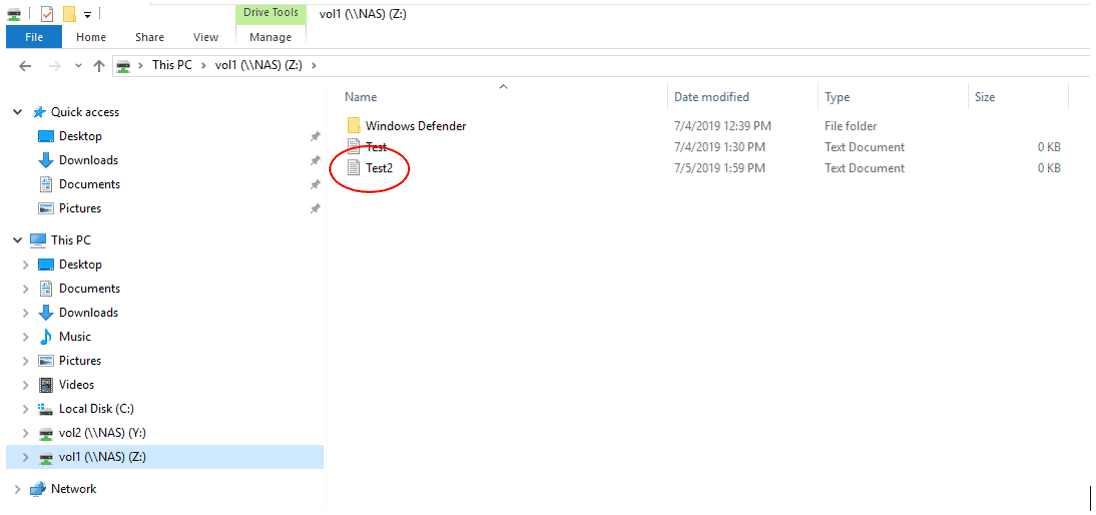
- Verify the volume is writeable by creating a new text file in it named Test2.


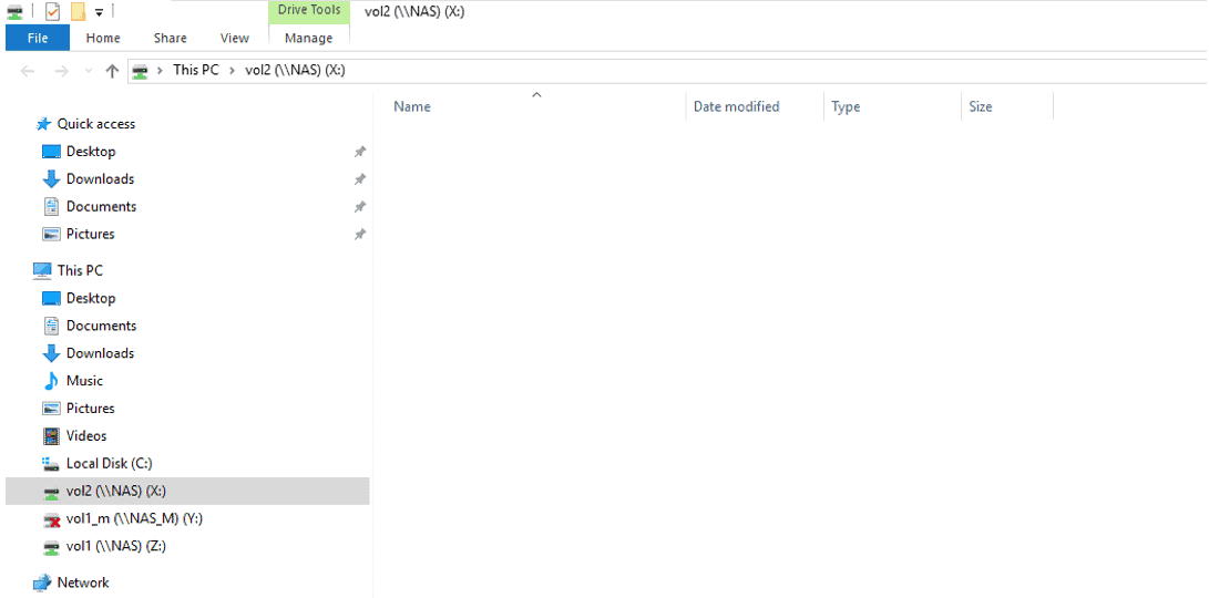
- Verify you can map a drive to the vol2


- Suspend the WinA virtual machine. (If your laptop has more than 18GB RAM you can leave the WinA virtual machine running.)
- Cluster1 has been recovered and you are ready to bring it back online as the primary site. Stop the NAS_DR SVM in Cluster2 to prevent a conflict when you bring Cluster1 back online.
cluster2::> vserver stop -vserver NAS_DR
[Job 56] Job succeeded: DONE
- Power on the C1N1 and C1N2 virtual machines. Set the Cluster1 date and time to match Cluster2.
cluster2::> cluster date show
Node Date Time zone
--------- ------------------------- -------------------------
cluster2-01
7/1/2019 01:59:00 -07:00 US/Pacific
1 entries were displayed.
The example below sets the date and time to 1st July 2019, 01:59am PST.
cluster1::> cluster date modify -dateandtime 201907010159
- Failback to Cluster1.
Any changes that were made to the data while Cluster1 was offline must be kept, and the SnapMirror relationship from Cluster1 to Cluster2 must be reinstated.
Create a SnapMirror relationship with the NAS_DR SVM in Cluster2 as the source and the NAS SVM in Cluster1 as the destination.
cluster1::> snapmirror create -destination-path NAS: -source-path NAS_DR: -type XDP -policy MirrorAllSnapshots -identity-preserve true
Replicate the data that was written to Cluster2 while Cluster1 was offline, back from the NAS_DR SVM to the NAS SVM.
cluster1::> snapmirror resync -destination-path NAS: -source-path NAS_DR:
Wait for the replication to complete.
cluster1::> snapmirror show
Progress
Source Destination Mirror Relationship Total Last
Path Type Path State Status Progress Healthy Updated
----------- ---- ------------ ------- -------------- --------- ------- --------
NAS_DR: XDP NAS: Snapmirrored
Idle - true -
cluster1://NAS/svm_root
LS cluster1://NAS/svm_root_m2
- - - - -
cluster1://NAS/svm_root_m1
- - - - -
3 entries were displayed.
Once the SVMs are back in sync, you can remove the SnapMirror relationship from Cluster2 to Cluster1.
cluster1::> snapmirror quiesce -destination-path NAS:
cluster1::> snapmirror break -destination-path NAS:
Notice: Volume quota and efficiency operations will be queued after "SnapMirror break" operation is complete. To check the status, run "job show -description "Vserverdr Break Callback job for Vserver : NAS"".
cluster1::> snapmirror delete -destination-path NAS:
cluster1::> snapmirror show
Progress
Source Destination Mirror Relationship Total Last
Path Type Path State Status Progress Healthy Updated
----------- ---- ------------ ------- -------------- --------- ------- --------
cluster1://NAS/svm_root
LS cluster1://NAS/svm_root_m2
Snapmirrored
Idle - true -
cluster1://NAS/svm_root_m1
Snapmirrored
Idle - true -
2 entries were displayed.
Then resync back from Cluster1 to Cluster2 to reinstate the original SnapMirror relationship.
cluster2::> snapmirror resync -destination-path NAS_DR:
Restart the CIFS service on the NAS SVM.
cluster1::> vserver cifs start -vserver NAS
- Verify the SnapMirror, SVM, volume and LIF settings are back to the same as before Cluster1 went offline.
Cluster1:
cluster1::> snapmirror show
Progress
Source Destination Mirror Relationship Total Last
Path Type Path State Status Progress Healthy Updated
----------- ---- ------------ ------- -------------- --------- ------- --------
cluster1://NAS/svm_root
LS cluster1://NAS/svm_root_m2
Snapmirrored
Idle - true -
cluster1://NAS/svm_root_m1
Snapmirrored
Idle - true -
2 entries were displayed.
cluster1::> snapmirror list-destinations
Progress
Source Destination Transfer Last Relationship
Path Type Path Status Progress Updated Id
----------- ----- ------------ ------- --------- ------------ ---------------
NAS: XDP NAS_DR: Transferring
103.7KB - 18d290ff-9fd6-11e9-9521-000c29adabc3
cluster1::> vserver show -vserver NAS -fields operational-state
vserver operational-state
------- -----------------
NAS running
cluster1::> volume show -vserver NAS
Vserver Volume Aggregate State Type Size Available Used%
--------- ------------ ------------ ---------- ---- ---------- ---------- -----
NAS svm_root aggr2_C1N1 online RW 20MB 18.42MB 3%
NAS svm_root_m1 aggr1_C1N1 online LS 20MB 18.64MB 1%
NAS svm_root_m2 aggr1_C1N2 online LS 20MB 18.64MB 1%
NAS vol1 aggr1_C1N1 online RW 100MB 80.30MB 15%
NAS vol2 aggr1_C1N2 online RW 100MB 93.55MB 1%
NAS vol3 aggr1_C1N2 online RW 100MB 94.75MB 0%
6 entries were displayed.
cluster1::> network interface show -vserver NAS
Logical Status Network Current Current Is
Vserver Interface Admin/Oper Address/Mask Node Port Home
----------- ---------- ---------- ------------------ ------------- ------- ----
NAS
NAS_cifs_lif1
up/up 172.23.2.21/24 cluster1-01 e0d true
NAS_cifs_lif2
up/up 172.23.2.22/24 cluster1-01 e0e true
NAS_cifs_lif3
up/up 172.23.2.23/24 cluster1-02 e0d true
NAS_cifs_lif4
up/up 172.23.2.24/24 cluster1-02 e0e true
4 entries were displayed.
Cluster2:
cluster2::> snapmirror show
Progress
Source Destination Mirror Relationship Total Last
Path Type Path State Status Progress Healthy Updated
----------- ---- ------------ ------- -------------- --------- ------- --------
NAS: XDP NAS_DR: Snapmirrored
Idle - true -
cluster2::> vserver show -vserver NAS_DR -fields operational-state
vserver operational-state
------- -----------------
NAS_DR stopped
cluster2::> volume show -vserver NAS_DR
Vserver Volume Aggregate State Type Size Available Used%
--------- ------------ ------------ ---------- ---- ---------- ---------- -----
NAS_DR svm_root aggr2_C2N1 online RW 20MB 18.68MB 1%
NAS_DR vol1 aggr2_C2N1 online DP 100MB 80.16MB 15%
NAS_DR vol2 aggr1_C2N1 online DP 100MB 94.65MB 0%
3 entries were displayed.
cluster2::> network interface show -vserver NAS_DR
Logical Status Network Current Current Is
Vserver Interface Admin/Oper Address/Mask Node Port Home
----------- ---------- ---------- ------------------ ------------- ------- ----
NAS_DR
NAS_cifs_lif1
up/down 172.23.2.21/24 cluster2-01 e0e true
NAS_cifs_lif2
up/down 172.23.2.22/24 cluster2-01 e0d true
NAS_cifs_lif3
up/down 172.23.2.23/24 cluster2-01 e0d true
NAS_cifs_lif4
up/down 172.23.2.24/24 cluster2-01 e0d true
4 entries were displayed.
- Suspend the C2N1 virtual machine and power on the WinA virtual machine. (You can leave C2N1 running if you have at least 18GB RAM on your laptop.)
- On Cluster1, set the date and time to match the WinA client. The example below sets the date and time to 20th March 2019, 09:23am PST.
cluster1::> cluster date modify -dateandtime 201903200923
- On the WinA host, verify the Test2.txt file you created in vol1 while it was failed over to the Cluster2 DR site is there.
You may need to hit F5 to refresh, or disconnect then reconnect the mapped network drive.
- Enable NDMP on the NAS SVM on Cluster1. The backup software will log in to the storage system using the vsadmin user account.
CIFS is the only allowed currently protocol on the NAS SVM.
cluster1::> vserver show-protocols
Vserver Name Protocols
--------------- ---------------
NAS cifs
cluster1 -
cluster1-01 -
cluster1-02 -
4 entries were displayed.
Allow NDMP.
cluster1::> vserver add-protocols -vserver NAS -protocols ndmp
Enable NDMP.
cluster1::> vserver services ndmp on -vserver NAS
Generate a password to be used by the backup software.
cluster1::> vserver services ndmp generate-password -vserver NAS -user vsadmin
Vserver: NAS
User: vsadmin
Password: 9Q0lUo8OBNRs4G1y
- Verify NDMP is enabled and its version.
cluster1::> vserver services ndmp show
VServer Enabled Authentication type
------------- --------- -------------------
NAS true challenge
cluster1 false challenge
2 entries were displayed.
cluster1::> vserver services ndmp version
VServer Version
------- --------
NAS 4
cluster1 4
2 entries were displayed.
Additional Resources
How to create mirror-vault and version flexible SnapMirror relationship on the vmstorageguy blog
SnapMirror Limitations from NetApp

Text by Alex Papas, Technical Writer at www.flackbox.com
Alex has been working with Data Center technologies for over 20 years. Currently he is the Network Lead for Costa, one of the largest agricultural companies in Australia. When he’s not knee deep in technology you can find Alex performing with his band 2am