
In this NetApp training tutorial, you’ll learn about how network load balancing and redundancy work for SAN protocols. Scroll down for the video and also text tutorials.
NetApp SAN Protocol Network Load Balancing and Redundancy Video Tutorial

Randy Johnson

The concepts, explanations, and applications to real world scenarios are exceptional. The hands-on labs reinforce the learning, and are actually better than the vendors’ labs.
I always feel fully engaged and fully oriented to the teaching. There has never been a time when I was scratching my head or not understanding the explanations or examples. And I can take the labs and examples and apply them directly in real environments.
Network Load Balancing
It is recommended to assign one data LIF per node, per protocol, per network, per SVM. That enables spreading out the overall load across all of your nodes and leverages all of the available hardware, including the CPU, RAM, etc., in all the nodes in your cluster.
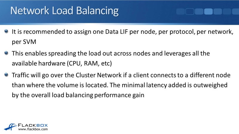
Traffic will go over the cluster network if a client connects to a different node than where the volume is located. That adds minimal latency, and that tiny amount of latency added is far outweighed by the benefits you get from the overall load balancing performance gain by spreading the traffic across all of the different nodes.
Let's have a look at how we're going to lay out our LIFs. Looking at an example here, we've got Department A SVM. They are using iSCSI, and they have got a LUN1 in Volume 1 and a LUN2 in Volume 2.
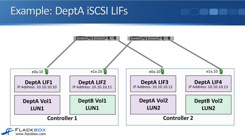
The LIFs that we configure for Department A iSCSI access are DeptA LIF1 with IP address 10.10.10.10, Dept A LIF2 with 10.10.10.11, LIF3 with 10.10.10.12, and LIF4 with 10.10.10.13.
You can see that on each of our nodes we've got two LIFs because we're connected to two separate networks.
We're going to have a Department B SVM as well, which is sharing the underlying physical ports. That's why, in this example, we're using VLAN interfaces e0a.10, e1a.10, e0a.10, and e1a.10 on the other node as well.
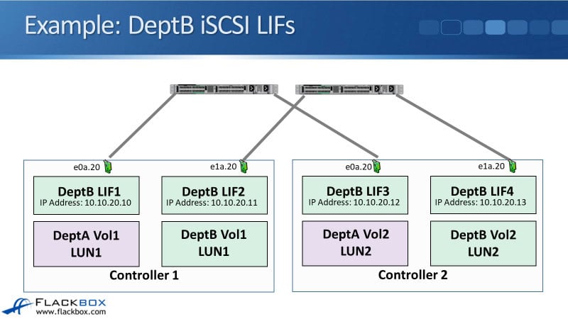
Department B is also using iSCSI. We've got DeptB Vol1 with LUN1 there and DeptB Vol2 with LUN2. We configured VLAN interfaces for Department B, so Department A was using 10.10.10.X and VLAN 10.
For this example, Department B is going to use 10.10.20.X and VLAN 20, and we configure that on each of the physical ports again.
Then our LIFs for Department B are going to be in a different IP subnet, so Department A was using 10.10.10.X, while Department B is using 10.10.20.X, and we're using .10, .11, .12, and .13 again. That's how we're laying out our LIFs for this example.
SAN Multipath
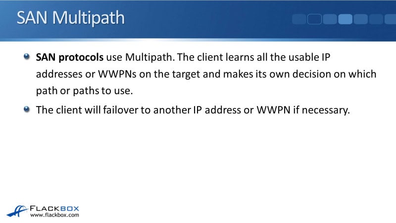
Now, our SAN protocols use multipath. The SAN client learns all of the usable IP addresses or WWPNs (if it's Fibre Channel) on the target, and the client can use that intelligence to make its own decision on which path or paths to use.
Because the client knows all the available paths, it can fail over to another IP address or WWPN if one or more of the paths it's using goes down.
Let's have a look and see how this is going to work. The client, which is the initiator, and the storage system, which is the target, are going to negotiate with each other. When you initially set this up, you tell the host one of the IP addresses on the storage system.
Let's say that this is a Department A client, and it's a client that is going to be using LUN1. On that Department A client, you configure it with one of these IP addresses. You configure either 10.10.10.10, .11, .12, or .13. It really doesn't matter which one. Just tell the client how it can reach its storage.
It will then connect to the storage system, and the client and the storage system will communicate with each other. The storage system will tell the client, "Hey, you can reach me through 10.10.10.10, .11, .12, or .13."
Optimized Path 1
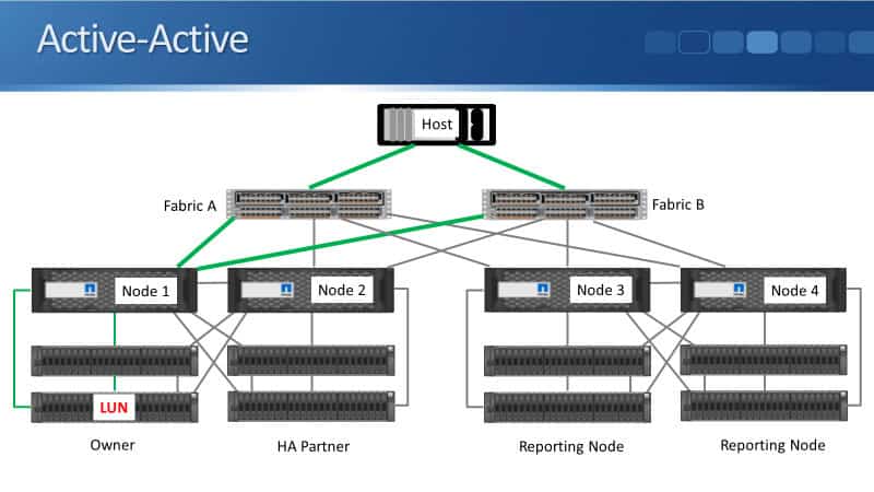
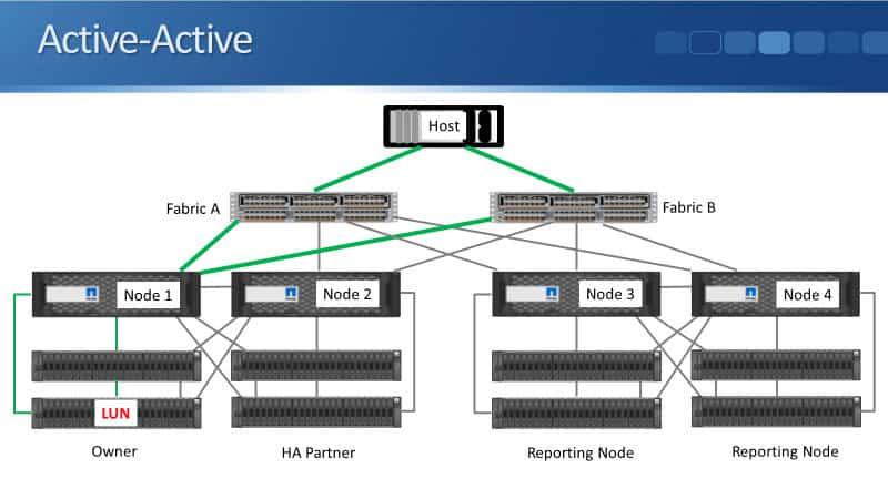
In our example, the LUN is on Node 1, so the storage system will tell the client that it can reach its LUN through this path, and it will say, "That is an optimized path." It's an optimized path because the connection terminates on the node that owns the LUN.
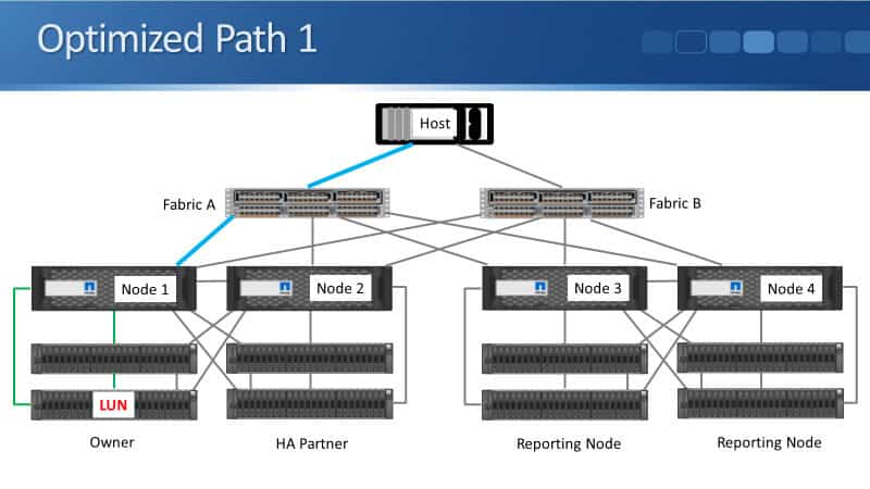
So, if the host is communicating directly with Node 1 over the network and sending reads or writes to its LUN, that's going to go straight through the SAS cables on Node 1 down to the disk shelf. That is the first optimized path, which goes through Fabric A and terminates on Node 1.
Optimized Path 2
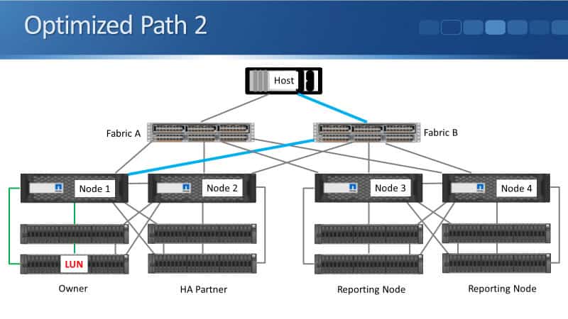
There's also another optimized path going through Fabric B, which also terminates on Node 1. That is an optimized path as well.
Non-Optimized Path 1
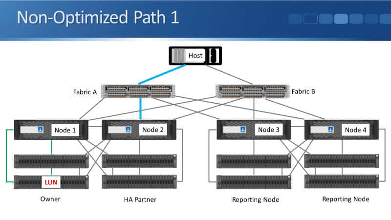
The storage system will also tell the client about the non-optimized paths. It will tell the host that it can reach its LUN through this path, which terminates on Node 2. Since Node 2 does not own the LUN, that is a non-optimized path. That path goes through the Fabric A switch.
Non-Optimized Path 2
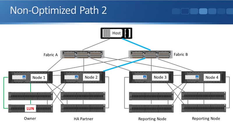
Finally, we've got another non-optimized path because it also terminates on a different node than the one that owns the LUN, and this one goes through Fabric B. So, the storage system tells the client, "Those are the four paths that you can use to get to your LUN. These are the two optimized paths, and you've also got two non-optimized paths."
Active-Active
Using the multipath software on the client side, you can configure whether you want to use active-active or active-standby. If you use active-active, the host is going to use both of its optimized paths to access its LUN. Those are the two active-active paths, and it will load-balance traffic across both of them.
Active-Active Path Fails
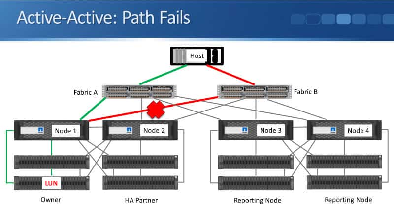
If one of the paths fails, in the example below, it's the connection between the node and the switch, the client will detect that the path has gone down and continue sending traffic through the remaining available path.
That gives us both load balancing and redundancy.
Active-Standby
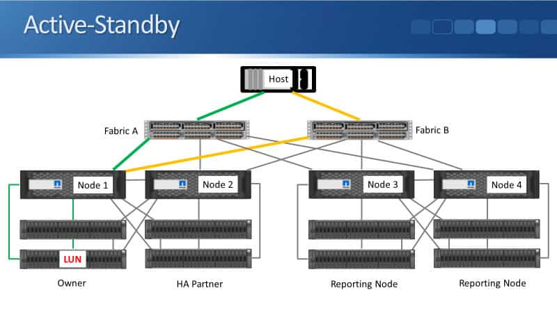
We can also optionally configure the client to use active-standby rather than active-active. In the example below, the client is using the green path. It also knows about the orange standby path.
Active-Standby Active Path Fails
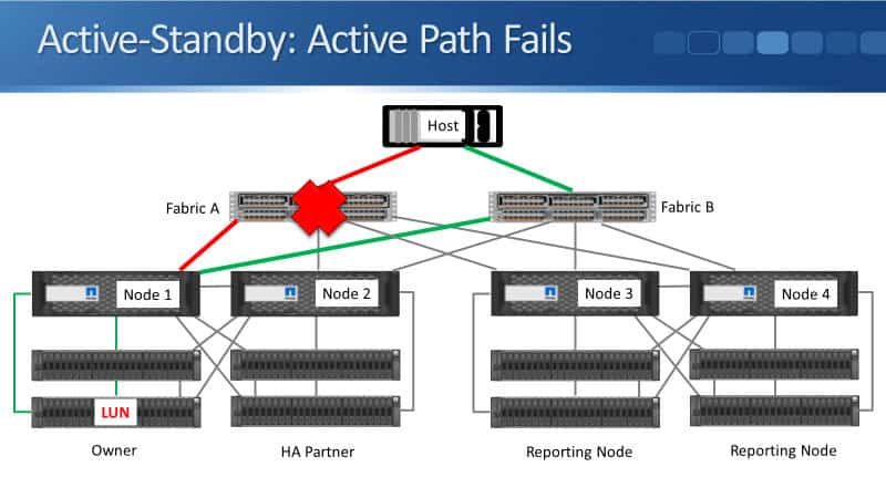
So, what happens is that if the active path goes down, if anything along that path fails, the client will detect it and transition to using the standby path, which now becomes the new active path. That provides redundancy.
Active-Active Node
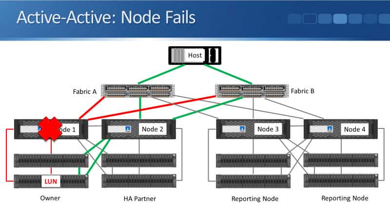
Another thing that could happen is that Node 1 fails. Here, we're looking at active-active again. The client is sending traffic through both available optimized paths, and then Node 1 fails.
Active-Active Node Fails
When Node 1 fails, the client detects that it has gone down. Node 2, being the HA partner of Node 1, also detects the failure. It takes ownership of Node 1's disks, and now the SAS cables on Node 2 connected to those disk shelves are used instead.
The client learns about its new best paths, and the traffic continues through the Fabric A and Fabric B switches. However, it now uses the connections that terminate on Node 2 instead of Node 1, allowing it to continue accessing its storage.
So, as you saw, with SAN protocols, load balancing and redundancy are built into the protocol itself. The initiator and the target communicate with each other. The initiator, which is the client, learns all of the available paths, including both optimized and non-optimized paths.
Using the multipath software on the client, you can configure whether to use active-active or active-standby. Because the client knows all of the available paths and their current status, if the path it is using fails, it automatically fails over to one of the remaining available paths.
Additional Resources
SAN Multipath and Automatic LIF Failover: https://docs.netapp.com/us-en/ontap/san-admin/multipath-automatic-lif-failover-support.html
Provisioning in SAN Environments: https://docs.netapp.com/us-en/ontap-apps-dbs/microsoft/win_san.html#provisioning-netapp-lun-on-windows-server
SAN Management Overview: https://docs.netapp.com/us-en/ontap/san-admin/
NetApp Network Load Balancing Tutorial: https://www.flackbox.com/netapp-network-load-balancing
Libby Teofilo

Text by Libby Teofilo, Technical Writer at www.flackbox.com
Libby’s passion for technology drives her to constantly learn and share her insights. When she’s not immersed in the tech world, she’s either lost in a good book with a cup of coffee or out exploring on her next adventure. Always curious, always inspired.