In this Cisco CCNA tutorial, we’re going to take a look at how switches learn MAC addresses and use that information to populate the MAC address table. Scroll down for the video and also text tutorial.
Cisco Switch Operation Video Tutorial

Charkrit Chantree

Passed the exam after a couple months of studying. Thank you Neil Anderson for providing a great course and helping me understand the concepts.
Switch Operation
For our first example, we've got one switch here. We've got a host with MAC address 1111.1111.1111 plugged into Port 1. I've just written it in shorthand here as 1.1.1 to keep things a bit more simple. 2.2.2 is plugged into Port 2 and 3.3.3 is plugged into Port 3. Right now, we've just powered everything on, so there's nothing in the MAC address table yet.

The host on the left, 1.1.1, sends a frame in with the destination MAC address of 2.2.2. The switch will see that. It sees a frame coming in with the source MAC of 1.1.1, the destination MAC of 2.2.2.

The switch learns that 1.1.1 is reachable on Port 1, and it puts that information into the MAC address table.

The destination of 2.2.2 is not in the MAC address table yet. It's an unknown unicast address, so the switch will flood it out all ports apart from the one it was received on. That will be sent out Ports 2 and 3. That will be received by both hosts.

Host 3.3.3 will see that the destination MAC address is 2.2.2. So, it will just silently discard the frame. The host of 2.2.2 is going to send some traffic back. It sends a reply from the source MAC of 2.2.2 itself to the destination MAC address of 1.1.1.

That will hit the switch again. The switch will see that traffic has come from a source of 2.2.2 and it came from Port 2. It will put that information into its MAC address table. Then, it will send the frame out only of Port 1, because it sees that the destination MAC address is 1.1.1. It knows that it's available on Port 1, so it sends it out only to that port.

That was how traffic works with a single switch. Now we're going to look at another example where we've got two switches. Switch 1 has got host 1.1.1 plugged into Port 1 and 2.2.2 plugged into Port 2. Switch 2 has got host 3.3.3 plugged into Port 1, and 4.4.4 plugged into Port 2. The two switches are connected to each other using Port 24 on both switches.

Again, we've just powered everything on, so there's nothing in the MAC address table on either switch yet. Then host 1.1.1 sends a frame in with a destination MAC address of 2.2.2.

Switch 1 will learn that 1.1.1 is available on Port 1, and it will put that information into its MAC address table.
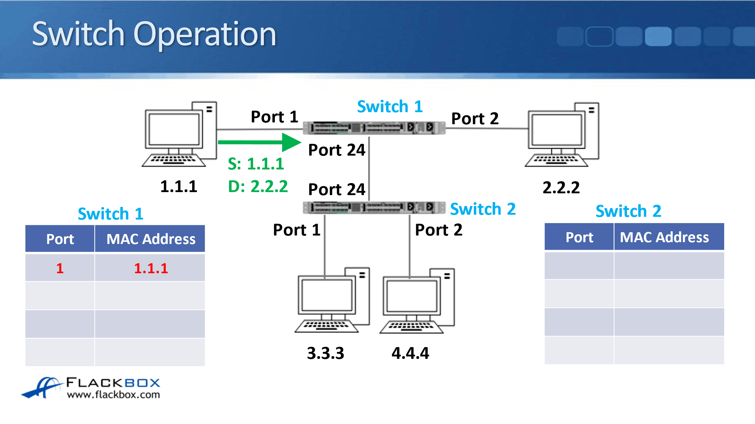
It will then flood the frame out all ports because it's an unknown unicast, it doesn't know where 2.2.2 is yet. So that will get sent out both Port 2 and Port 24.

When it comes to Switch 2, Switch 2 will do the same thing. It will flood it out all ports. That will be sent out Port 1 and Port 2 as well. The hosts 3.3.3 and 4.4.4 will see that the destination MAC address is 2.2.2, that's not for them. So, they will silently drop the packet.
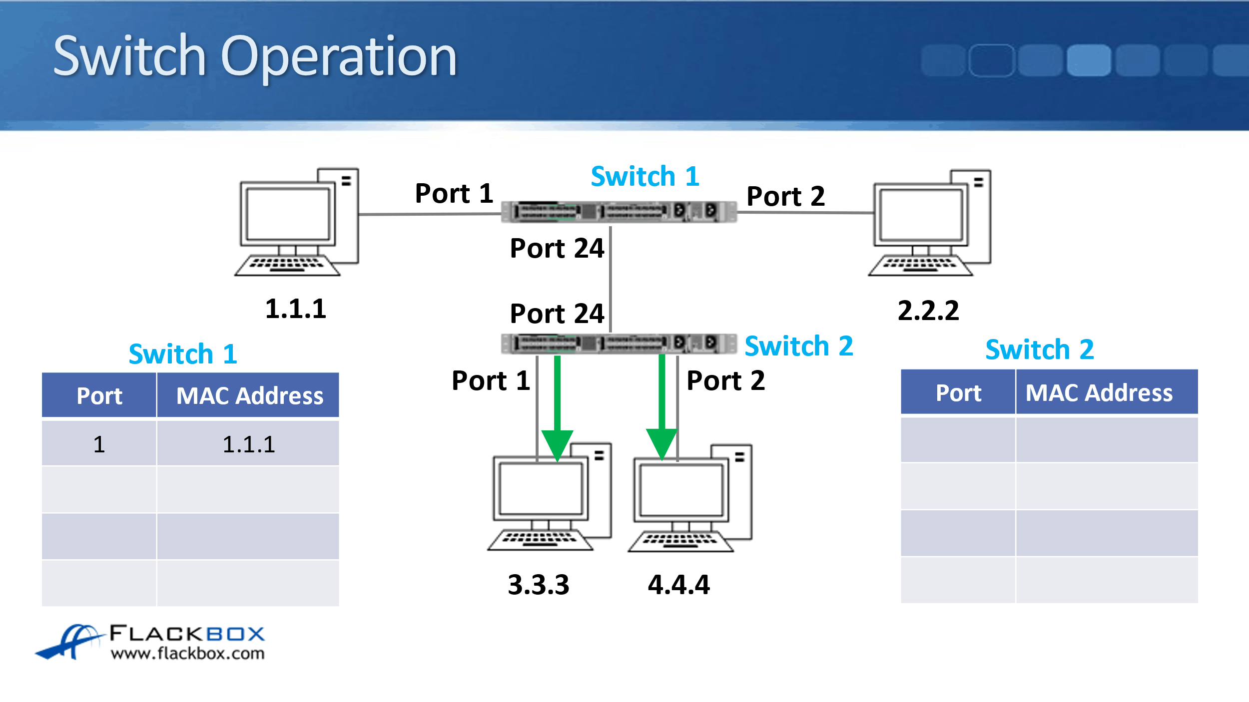
While that is happening, Switch 2 will update its MAC address table. It learned that 1.1.1 was reachable through Port 24 because that's the port that the frame came in on.

The frame will have reached 2.2.2. It's going to send some return traffic, so that will hit Switch 1 with a source MAC of 2.2.2, and a destination MAC address of 1.1.1.

Switch 1 will update its MAC address table with the entry for 2.2.2 to say it is reachable on Port 2.

Switch 1 will then forward the frame out Port 1, because it already knows that the MAC address of 1.1.1 is reachable through there, it's in its MAC address table. Notice that the frame does not get sent down to Switch 2 now, because Switch 1 knew that it should go out only on Port 1.

The next thing that happens is we're going to have some different traffic. Now, the source of 3.3.3 sends a frame to the destination MAC address of 2.2.2.
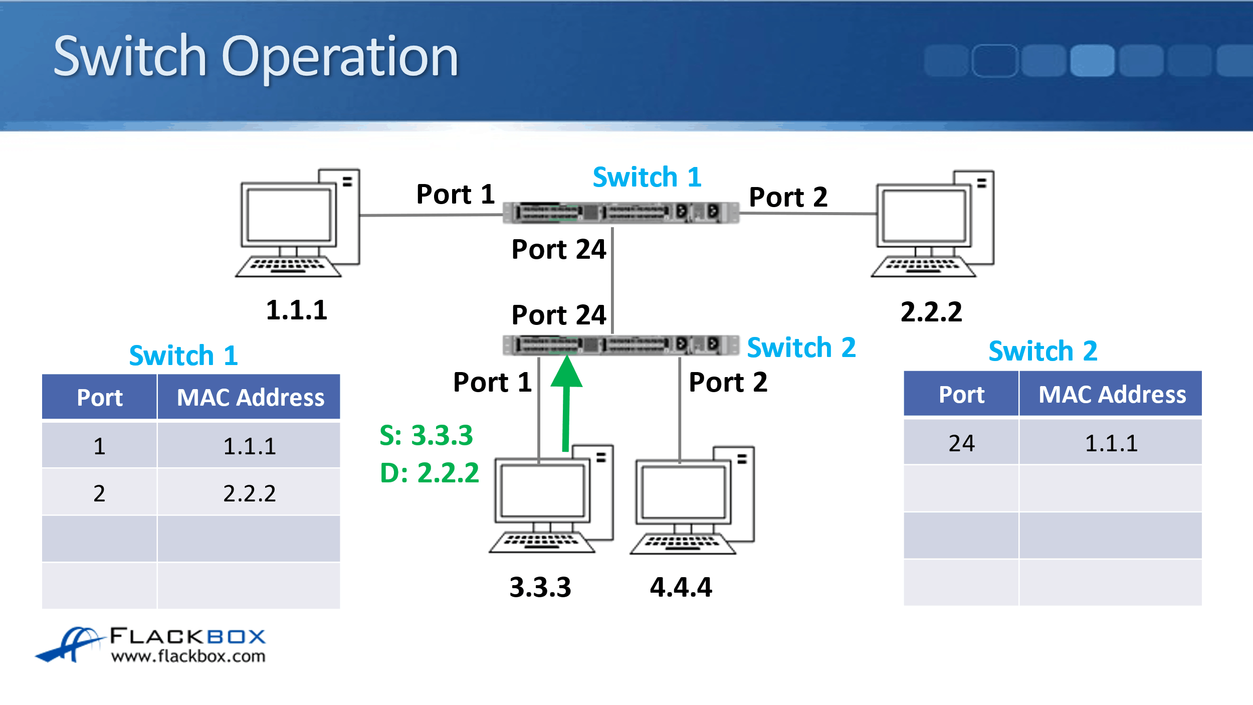
That hits Switch 2, and it will update its MAC address table to say that host 3.3.3 is reachable on Port 1.
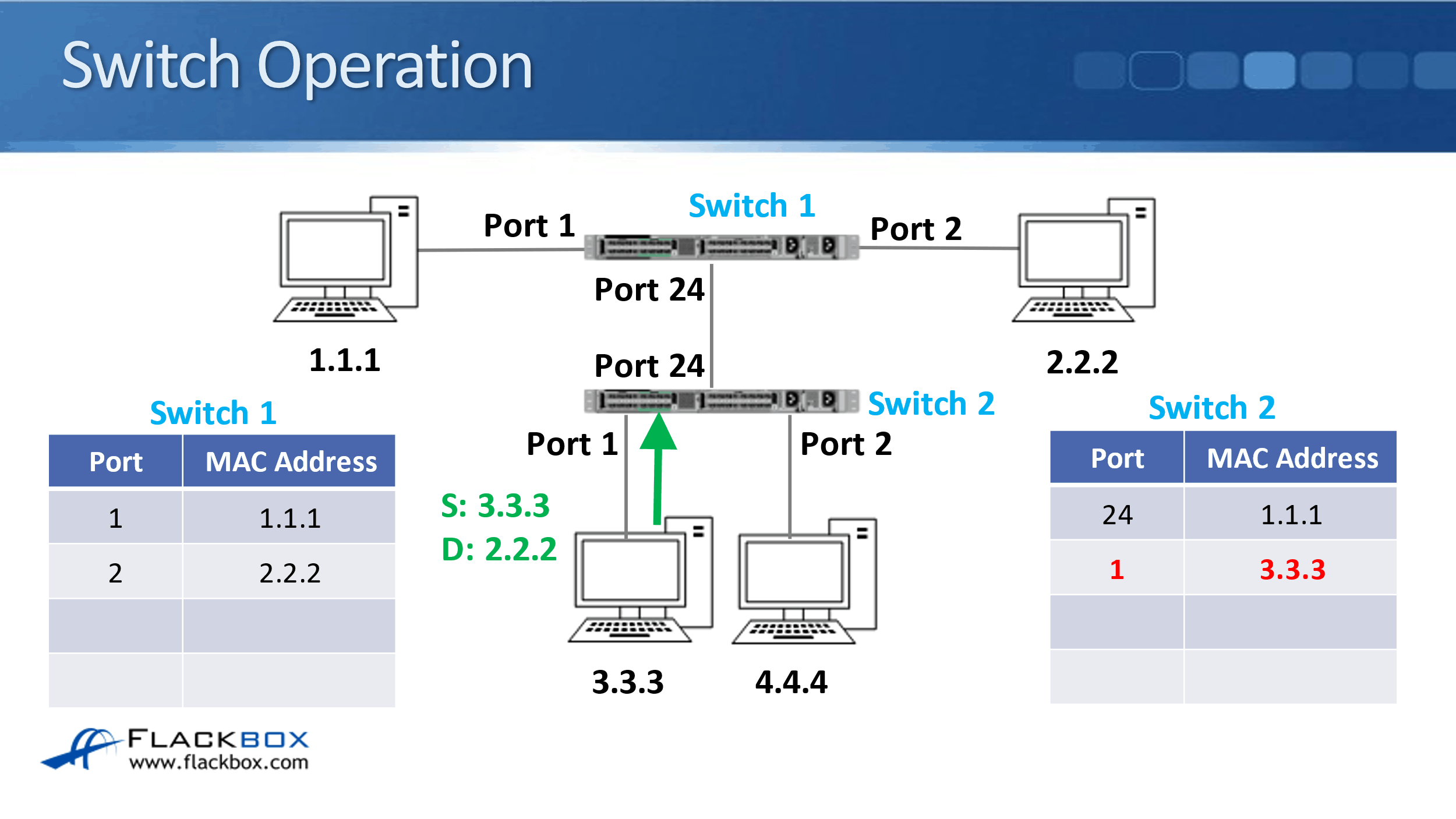
Switch 2 will then forward that frame out all ports because the destination MAC address was 2.2.2, and it doesn't have that in its MAC address table. It's an unknown unicast, it will send it everywhere.
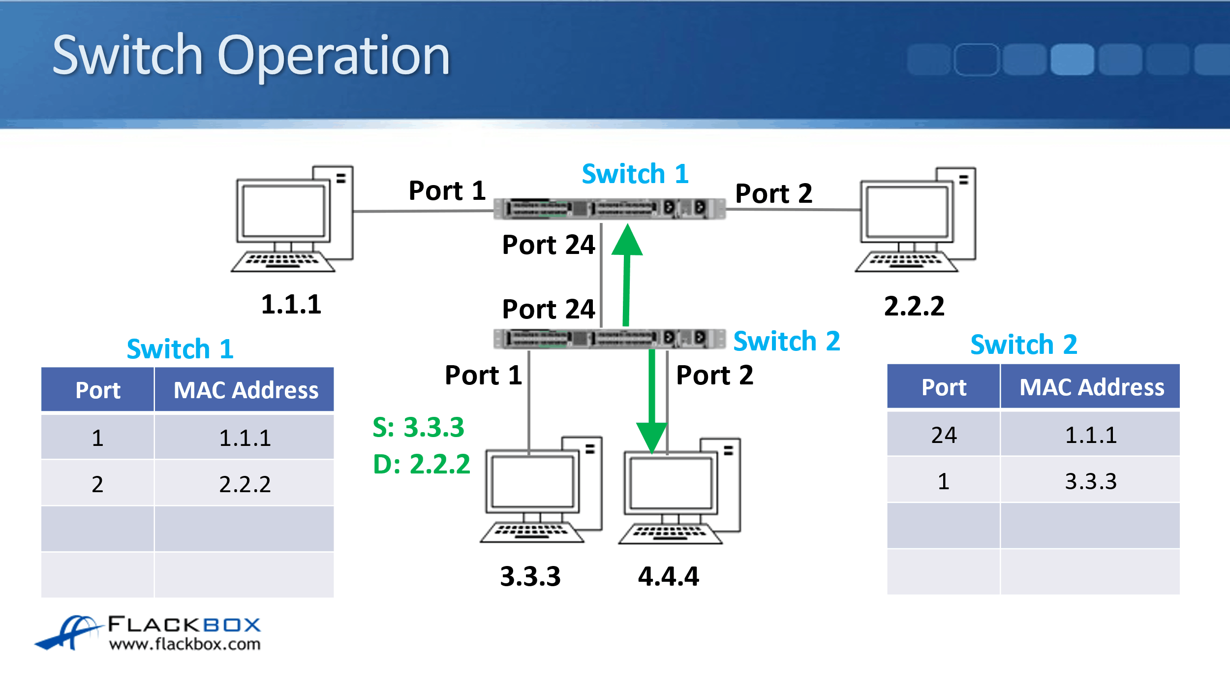
That will hit Switch 1 and Switch 1 will see the frame arriving on Port 24 that came with a source MAC address of 3.3.3. So, it will put that information in its MAC address table.
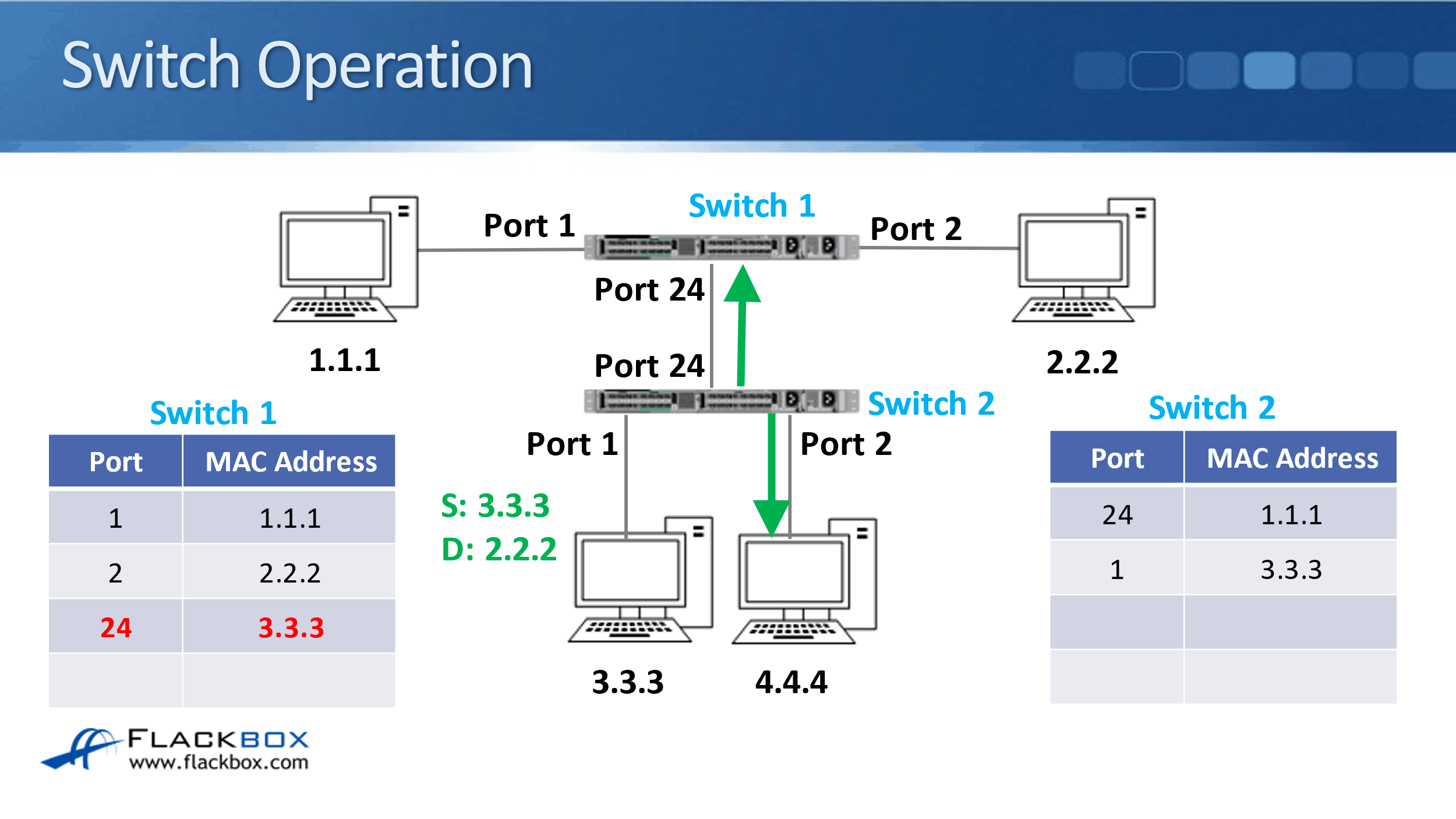
It will then send the frame out of Port 2, to the destination of 2.2.2, because it already had that in its MAC address table. It just sends it out that one relevant port.
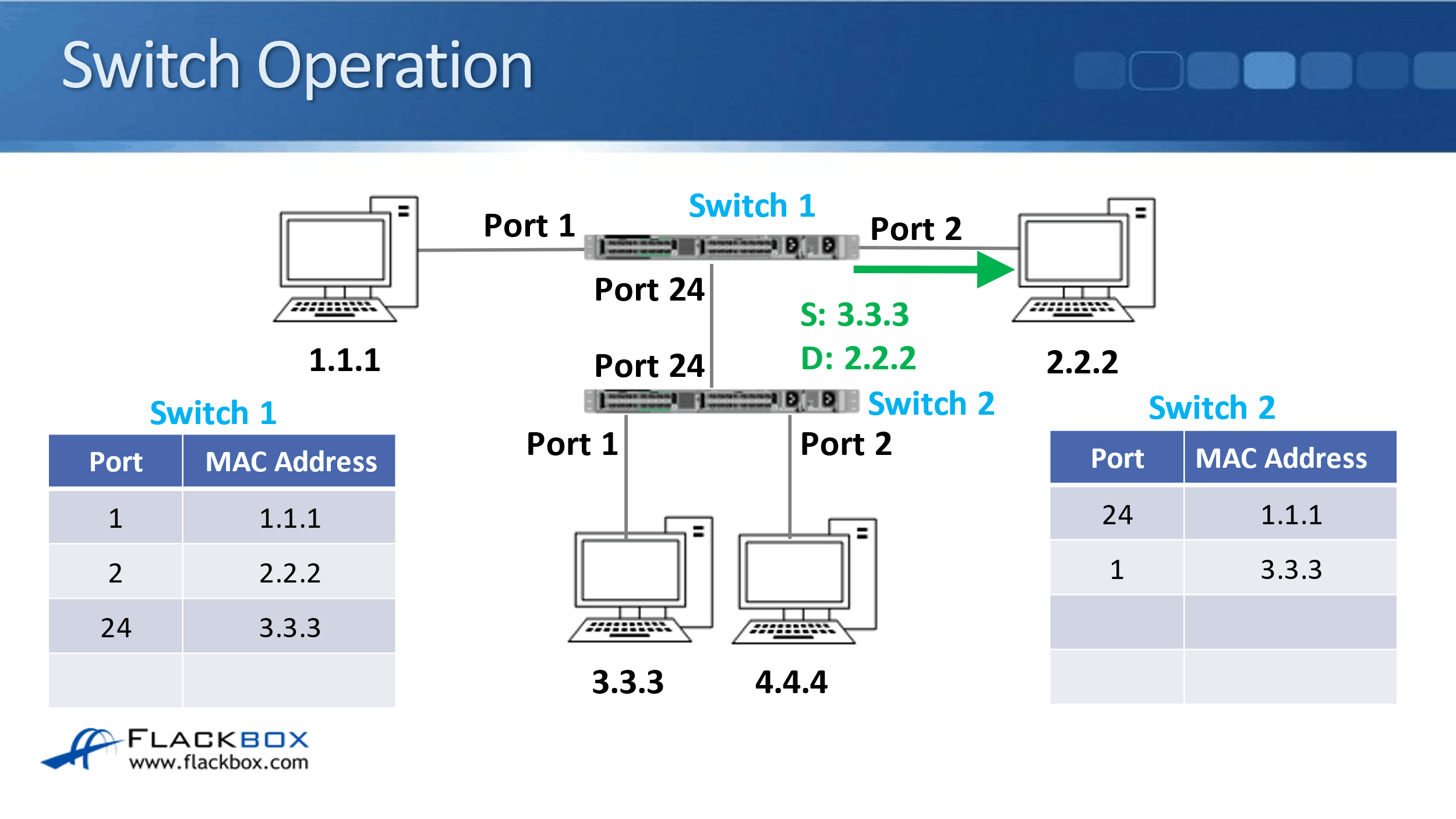
Then host 2.2.2 sends some return traffic back to the destination MAC address of 3.3.3, and that hits Switch 1.
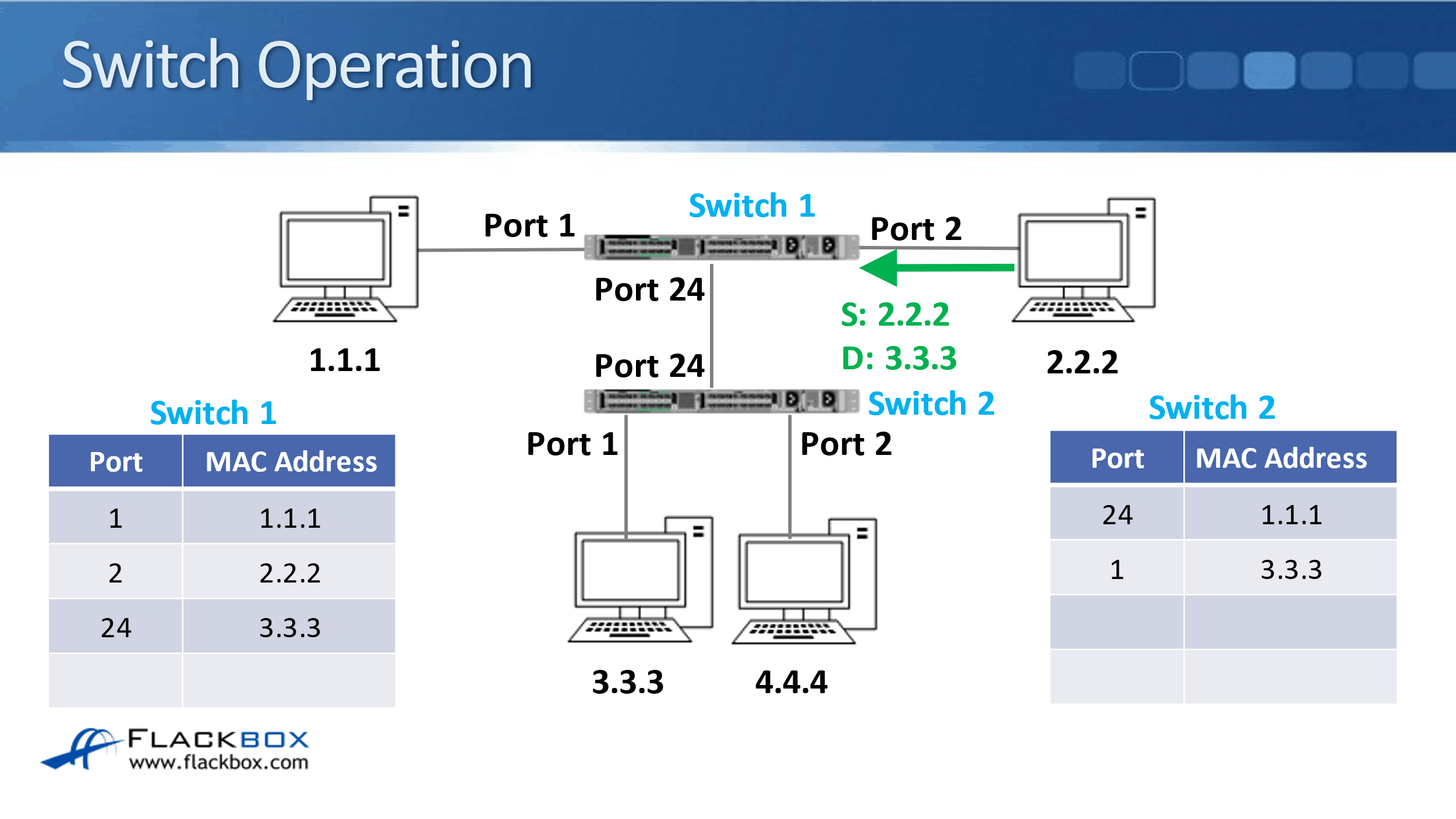
Switch 1 does have 3.3.3 in its MAC address table. It sees that it's reachable through Port 24. So, it sends it out just that port.
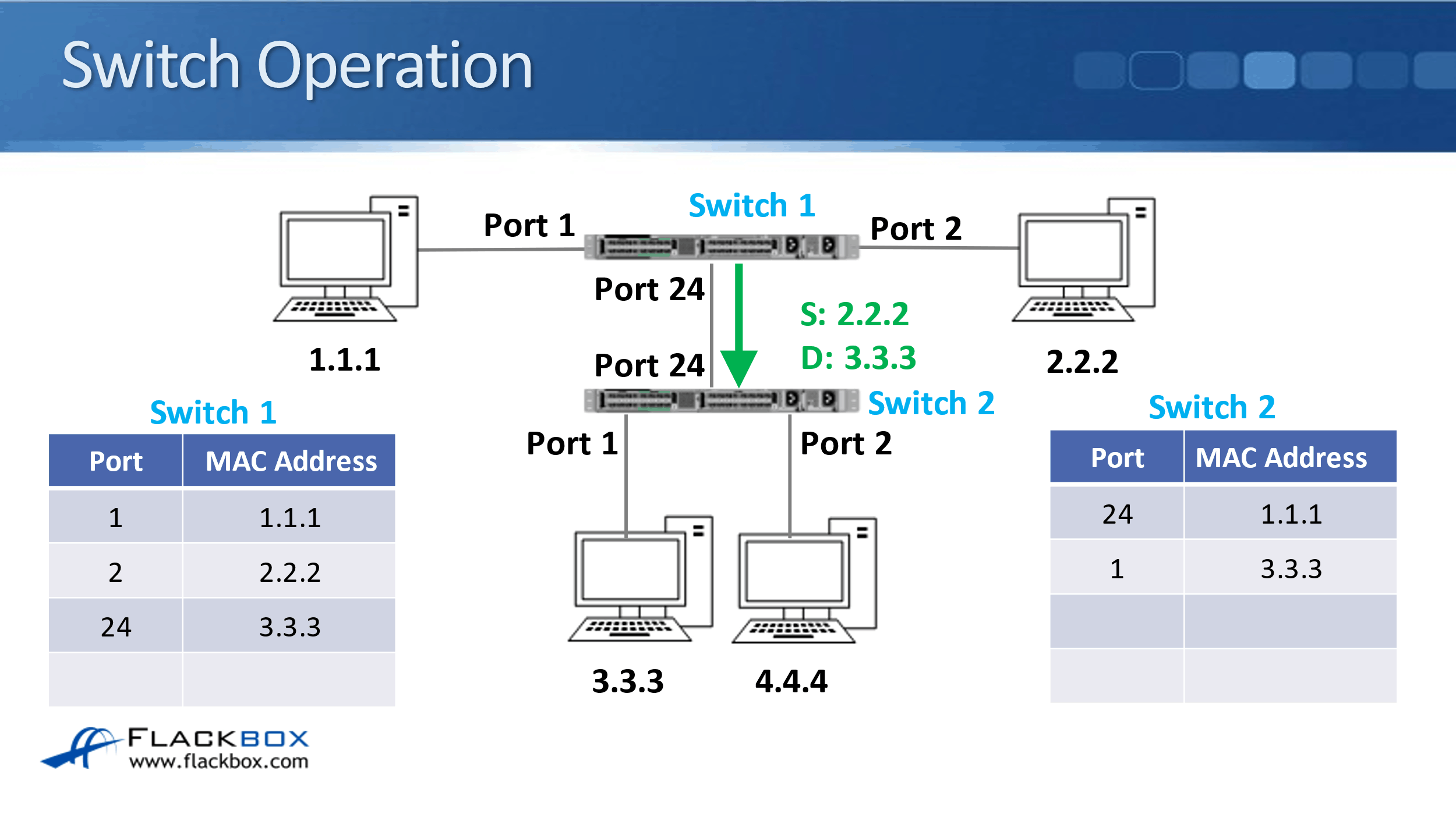
The traffic will then hit Switch 2. Switch 2 sees traffic coming in from a source MAC address of 2.2.2 on Port 24. Therefore, it will update its MAC address table with that information.
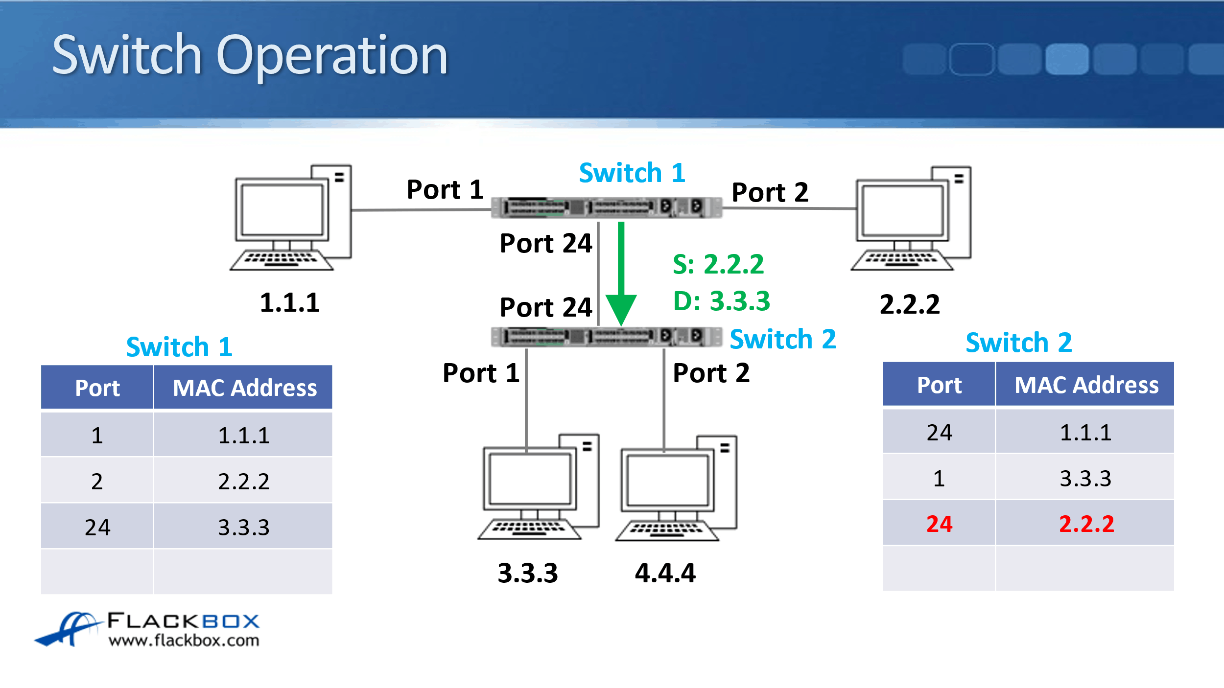
It will then forward the frame out Port 1 only because it knows that 3.3.3 is available out of that port. If you look at the MAC address table for Switch 2 now, you can see that 1.1.1 and 2.2.2 are both reachable on Port 24.
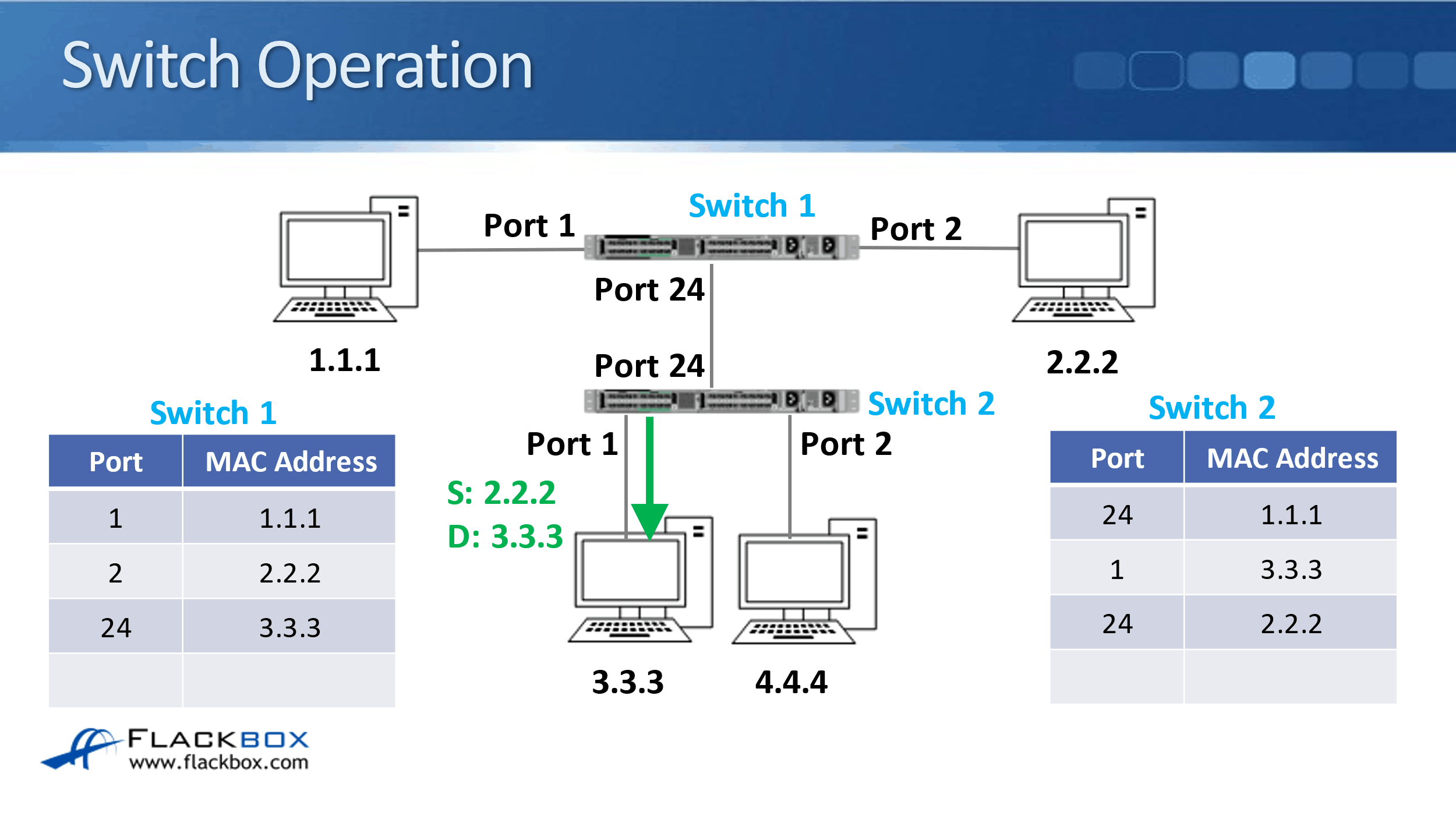
This is what you'll see in normal practice as well. If a switch has got a single end host plugged into it on a port, then it will just have that one MAC address on that port in its MAC address table. However, if a switch is connected to another switch, you'll see there will be multiple MAC addresses reachable on that port.
Cisco Switch Operation Configuration Example
This configuration example is taken from my free ‘Cisco CCNA Lab Guide’ which includes over 350 pages of lab exercises and full instructions to set up the lab for free on your laptop.
Click here to download your free Cisco CCNA Lab Guide.
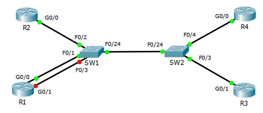
- Log into routers R1 to R4 and verify which interface is configured on the 10.10.10.0/24 network.
R1#show ip interface brief
Interface IP-Address OK? Method Status Protocol
GigabitEthernet0/0 10.10.10.1 YES manual up up
GigabitEthernet0/1 unassigned YES unset administratively down down
GigabitEthernet0/2 unassigned YES unset administratively down down
Vlan1 unassigned YES unset administratively down down
R2#show ip interface brief
Interface IP-Address OK? Method Status Protocol
GigabitEthernet0/0 10.10.10.2 YES manual up up
GigabitEthernet0/1 unassigned YES unset administratively down down
GigabitEthernet0/2 unassigned YES unset administratively down down
Vlan1 unassigned YES unset administratively down down
R3#show ip interface brief
Interface IP-Address OK? Method Status Protocol
GigabitEthernet0/0 unassigned YES unset administratively down down
GigabitEthernet0/1 10.10.10.3 YES manual up up
GigabitEthernet0/2 unassigned YES unset administratively down down
Vlan1 unassigned YES unset administratively down down
R4#show ip interface brief
Interface IP-Address OK? Method Status Protocol
GigabitEthernet0/0 10.10.10.4 YES manual up up
GigabitEthernet0/1 unassigned YES unset administratively down down
GigabitEthernet0/2 unassigned YES unset administratively down down
Vlan1 unassigned YES unset administratively down down
R1, R2 and R4 are using GigabitEthernet0/0, R3 is using GigabitEthernet0/1.
2. Note down the MAC addresses of these interfaces.
R1#show interface gig0/0
GigabitEthernet0/0 is up, line protocol is up (connected)
Hardware is CN Gigabit Ethernet, address is 0090.2b82.ab01 (bia 0090.2b82.ab01)
R2#show interface gig0/0
GigabitEthernet0/0 is up, line protocol is up (connected)
Hardware is CN Gigabit Ethernet, address is 0060.2fb3.9152 (bia 0060.2fb3.9152)
R3#show interface gig0/1
GigabitEthernet0/1 is up, line protocol is up (connected)
Hardware is CN Gigabit Ethernet, address is 0001.9626.8970 (bia 0001.9626.8970)
R4#show interface gig0/0
GigabitEthernet0/0 is up, line protocol is up (connected)
Hardware is CN Gigabit Ethernet, address is 00d0.9701.02a9 (bia 00d0.9701.02a9)
Note: the MAC addresses in your lab may be different.
3. Verify connectivity between the routers by pinging R2, R3, and R4 from R1.
R1#ping 10.10.10.2
Type escape sequence to abort.
Sending 5, 100-byte ICMP Echos to 10.10.10.2, timeout is 2 seconds:
.!!!!
Success rate is 80 percent (4/5), round-trip min/avg/max = 0/0/3 ms
R1#ping 10.10.10.3
Type escape sequence to abort.
Sending 5, 100-byte ICMP Echos to 10.10.10.3, timeout is 2 seconds:
.!!!!
Success rate is 80 percent (4/5), round-trip min/avg/max = 0/0/1 ms
R1#ping 10.10.10.4
Type escape sequence to abort.
Sending 5, 100-byte ICMP Echos to 10.10.10.4, timeout is 2 seconds:
.!!!!
Success rate is 80 percent (4/5), round-trip min/avg/max = 0/0/1 ms
4. Ping R3 and R4 from R2.
R2#ping 10.10.10.3
Type escape sequence to abort.
Sending 5, 100-byte ICMP Echos to 10.10.10.3, timeout is 2 seconds:
.!!!!
Success rate is 80 percent (4/5), round-trip min/avg/max = 0/0/1 ms
R2#ping 10.10.10.4
Type escape sequence to abort.
Sending 5, 100-byte ICMP Echos to 10.10.10.4, timeout is 2 seconds:
.!!!!
Success rate is 80 percent (4/5), round-trip min/avg/max = 0/0/1 ms
5. View the dynamically learned MAC addresses on SW1 and verify that the router’s MAC addresses are reachable via the expected ports. Ignore any other MAC addresses in the table.
SW1#show mac address-table dynamic
Mac Address Table
-------------------------------------------
Vlan Mac Address Type Ports
---- ----------- -------- -----
1 0001.9626.8970 DYNAMIC Fa0/24
1 000c.cf84.8418 DYNAMIC Fa0/24
1 0060.2fb3.9152 DYNAMIC Fa0/2
1 0090.2b82.ab01 DYNAMIC Fa0/1
1 00d0.9701.02a9 DYNAMIC Fa0/24
6. Repeat on SW2.
SW2#show mac address-table dynamic
Mac Address Table
-------------------------------------------
Vlan Mac Address Type Ports
---- ----------- -------- -----
1 0001.9626.8970 DYNAMIC Fa0/3
1 000b.be53.6418 DYNAMIC Fa0/24
1 0060.2fb3.9152 DYNAMIC Fa0/24
1 0090.2b82.ab01 DYNAMIC Fa0/24
1 00d0.9701.02a9 DYNAMIC Fa0/4
7. Clear the dynamic MAC Address Table on SW1.
SW1#clear mac address-table dynamic
8. Show the dynamic MAC Address Table on SW1. Do you see any MAC addresses? Why or why not?
SW1#show mac address-table dynamic
Mac Address Table
-------------------------------------------
Vlan Mac Address Type Ports
---- ----------- -------- -----
1 0001.9626.8970 DYNAMIC Fa0/24
1 000c.cf84.8418 DYNAMIC Fa0/24
1 0060.2fb3.9152 DYNAMIC Fa0/2
1 0090.2b82.ab01 DYNAMIC Fa0/1
1 00d0.9701.02a9 DYNAMIC Fa0/24
Devices in a real world network tend to be chatty and send traffic frequently, this causes the MAC address table to update (you may see less entries in Packet Tracer).
The switch will periodically flush old entries.
Additional Resources
How Does a Switch Work?: https://www.cisco.com/c/en/us/solutions/small-business/resource-center/networking/network-switch-how.html
Basic Switch Operation: https://www.oreilly.com/library/view/ethernet-switches/9781449367299/ch01.html
How a LAN Switch Works: https://www.ciscopress.com/articles/article.asp?p=357103&seqNum=4
Libby Teofilo

Text by Libby Teofilo, Technical Writer at www.flackbox.com
Libby’s passion for technology drives her to constantly learn and share her insights. When she’s not immersed in the tech world, she’s either lost in a good book with a cup of coffee or out exploring on her next adventure. Always curious, always inspired.