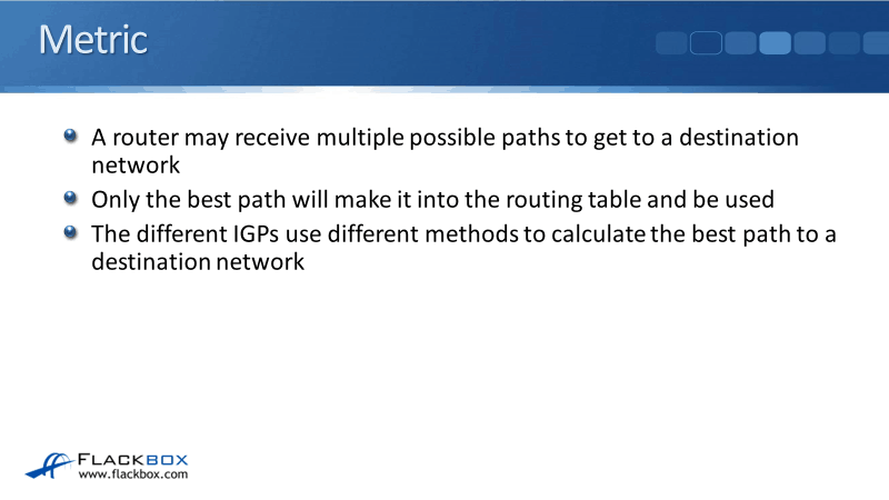
In this Cisco CCNA training tutorial, you’ll learn about routing protocol metrics. A router may receive multiple possible paths to get to a destination network because it might have multiple different ways to get to it.
The router might have multiple neighboring routers with paths available through all of them. Scroll down for the video and text tutorial.
Cisco Routing Protocol Metrics Title Video Tutorial
Austin Crews

Passed my CCNA yesterday Neil!!! First time go!!! Thanks again for all the work you put into your course, it was the best money I have ever spent!
Out of all the paths that the router knows about, only the best path is going to make it into the routing table and be used. Thus, the different interior gateway protocols need some way to determine which is the best path by using different calculation methods.
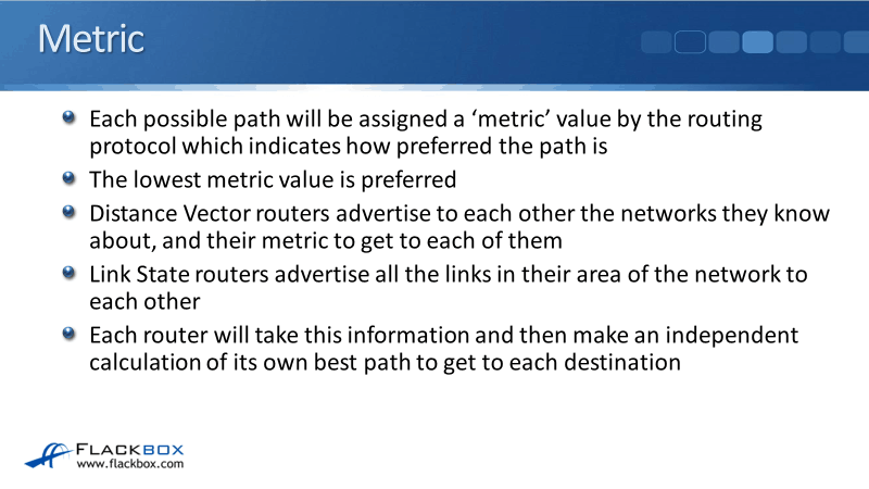
Each possible path will be assigned a metric value by the routing protocol which indicates how preferred the path is. The path with the lowest metric value is the most preferred path.
An easy way to remember this is, in OSPF, the term for metric is cost. Just like when you go shopping, the lower the cost of something, the better it is. Remember, the lower the cost or the lower the metric, the more preferred the path is going to be.
- Distance vector routers advertise to each other the networks they know about and their metric to get to each of them.
- Link state routers advertise all the links in the area of the network to each other. Each router will take that information and then use it to make an independent calculation of its own best path to get to each destination.
If the best path to a destination is lost, for example, a link went down, it will be removed from the routing table and will be replaced with the next best route. The route that has the next lowest metric will be chosen, if one is available.
This is a big advantage of the dynamic routing protocols, they're self-healing. If anything changes on the network, the routing tables will be updated to reflect the changes.
RIP Metric – Hop Count
Let's take a look at the different methods and metrics that are used by our different routing protocols.
The Routing Information Protocol (RIP) always uses hop count as the metric. A hop means going through another router. Hop count is the number of routers the router has to go through to get to the destination network.
The default maximum hop count in RIP is 15. Paths that are more than 15 hops away are marked as unreachable by default. Therefore, there is a scalability limitation with RIP.
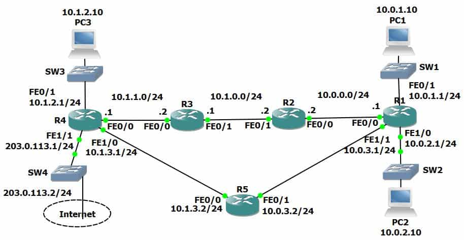
In the example below, we've got network 10.0.1.0/24 connected behind R1. From R4, all the links in the top path are a hundred megabits per second links. The links going down via R5 are all 10 megabits per second links.
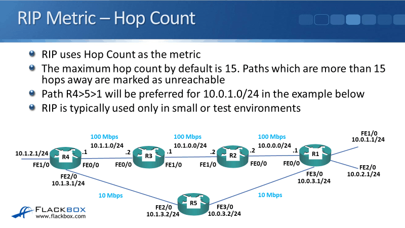
RIP will prefer the bottom path because it will take two hops to go from R4 to R5 to R1, rather than three hops going via R3, R2, and R1.
So, you can see a problem with RIP here. It will always use the path with the shortest hop count even if those links are low bandwidth links which would really not be the best path.
Because of the scalability limitation and the inconsideration of the links’ bandwidth, RIP is not normally used in production networks. It is used in really small networks or in test environments.
Let's go through an example of how the metric is going to work in RIP.
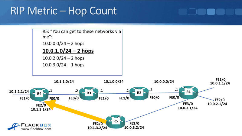
R1 has formed an adjacency with R2 and it will say that "Okay, R2, you can get to these networks via me. 10.0.1.0/24, which is going to cost you one hop, 10.0.2.0/24 and 10.0.3.0/24, which are also one hop away, 10.1.3.0/24 is two hops away, and 10.1.2.0/24 is three hops away."
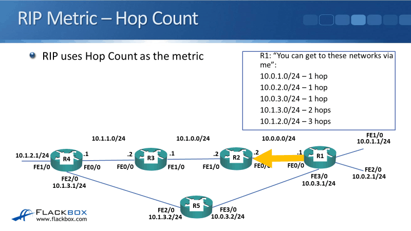
The first three networks, 10.0.1.0/24, 10.0.2.0/24, and 10.0.3.0/24 are all directly connected to R1. 10.1.3.0/24 is behind R5 and 10.1.2.0/24 is behind R4 from R1's point of view so they have an additional one or two hops away.
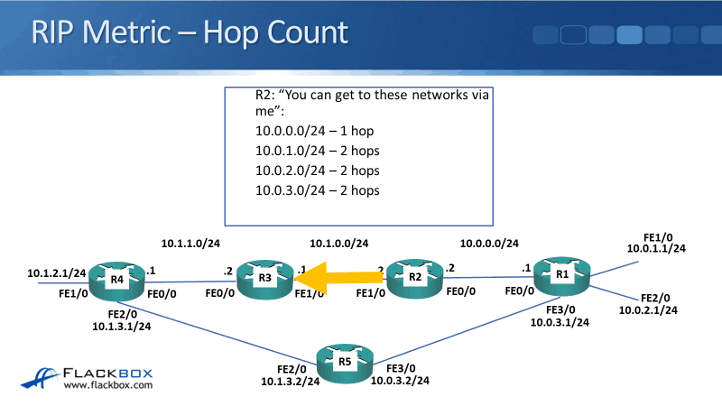
R2 will get that information and it will update its routing table. It will then pass the information on to R3. So R2 will say "Hey, R3, you can get to these networks via me. 10.0.0.0/24 is one hop because I’m directly connected to it, 10.0.1.0/24, 10.0.2.0/24, and 10.0.3.0/24 are two hops away."
R3 will then pass that information on to R4, and it will tell R4, "You can get to 10.0.0.0/24 through me. It will cost you two hops. 10.0.1.0/24 and 10.0.2.0/24 are three hops away, and 10.1.0.0/24 is one hop away."
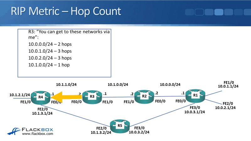
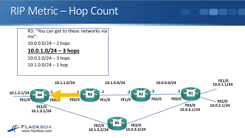
If we look at the information that reached R4 from R3, R3 told it that "You can get to the 10.0.1.0/24 network through me and it's going to be three hops." That was along the top path.
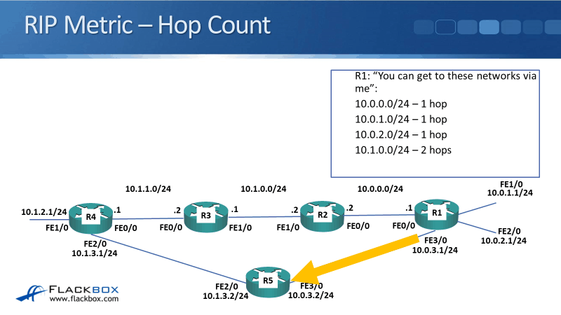
R1 is also directly connected to R5 and we're running RIP everywhere, so it will form an adjacency with R5 as well. R1 will send updates and will tell R5 that "You can get to 10.0.0.0/24, 10.0.1.0/24, and 10.0.2.0/24 which is one hop because we are directly connected. 10.1.0.0/24 is two hops."
It sends that information to R5 and R5 will update its routing table. It will then pass the information to R4 and will say, "You can get to 10.0.0.0/24, 10.0.1.0/24, and 10.0.2.0/24 through me. It will be two hops. 10.0.3.0/24 will be one hop."
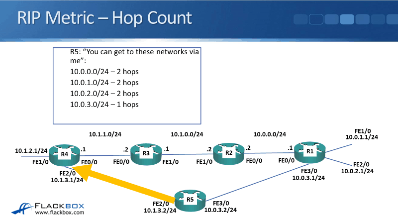
Along the top path, R3 told R4, "You can get to the 10.0.1.0/24 network and it's three hops away." R5 also advertises the 10.0.1.0/24 network, but it's only two hops away.
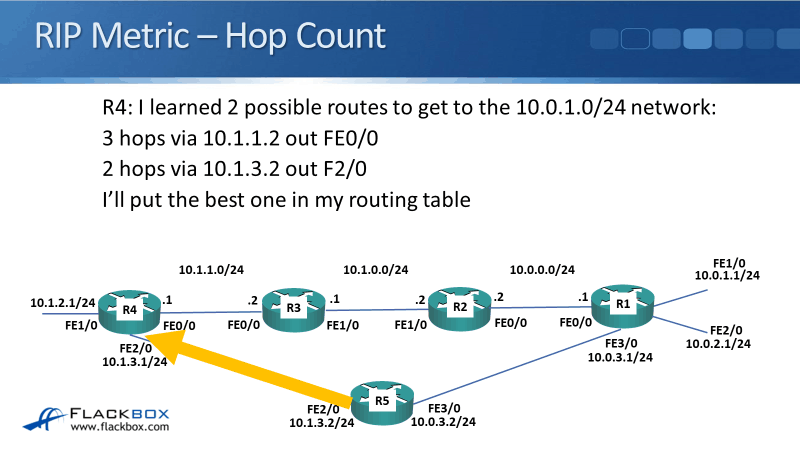
R4 learns two potential paths it can use to get to the 10.0.1.0/24 network. R4 can either go through:
- R3 - Three hops away
- R5 - Two hops away
The route via R5 is going to make into the routing table because it has the best metric. Both routes will be there in the database but, it's only the best one with the lowest metric that actually makes it into the routing table.
So R4 says, "I learned those two possible routes to get to 10.0.1.0/24 network. Three hops via 10.1.1.2 out FastEthernet0/0 interface, two hops via 10.1.3.2 out FastEthernet2/0.” Then it puts the best route in the routing table, which is via R5.
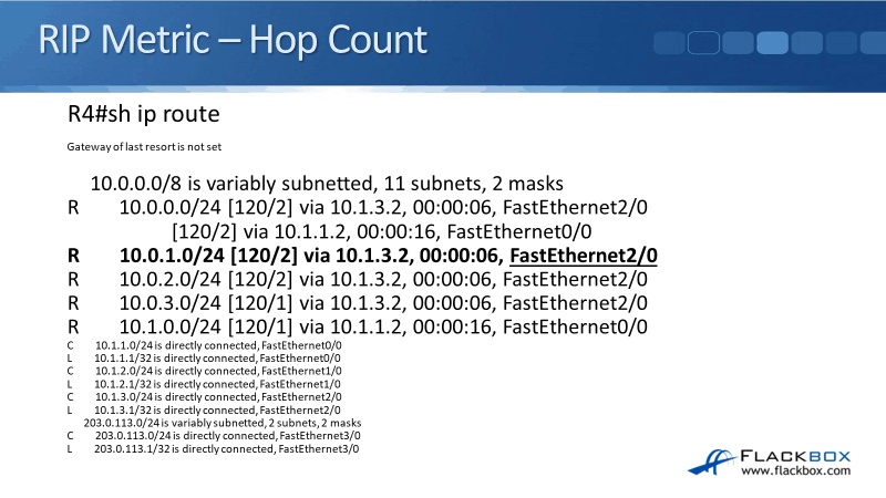
The command show ip route shows that the one best route via R5 has made it into the routing table.
The problem with RIP is that it uses hop count. The traffic will always go along the worse bottom path with 10 megabits per second links. We would actually prefer the traffic to go across the top path with 100 megabits per second links.
OSPF Metric - Cost
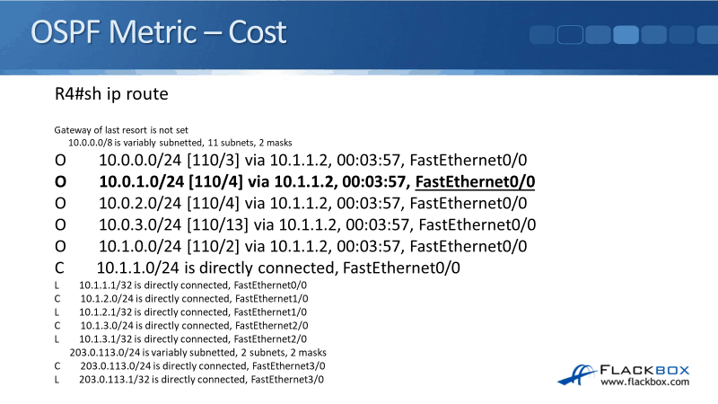
Compared to RIP, OSPF takes bandwidth into account. It uses cost as the metric which is automatically derived from the interface bandwidth by default. The cost of links can be manually configured to manipulate the path but OSPF is going to take the best path anyway.
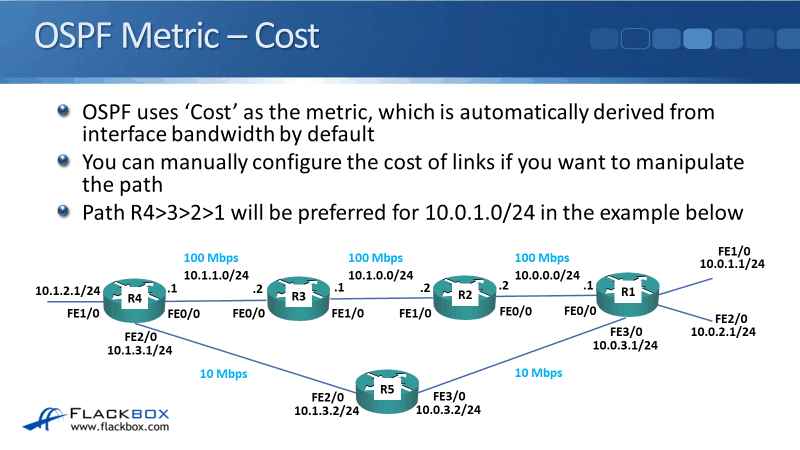
In our example, using OSPF will prefer the path from R4 to R3 to R2 to R1 for the 10.0.1.0/24 network. Unlike RIP, which used hop count and went along the bottom path, OSPF is going to use cost which takes the bandwidth into account. Therefore, R4 is going to go along the top path because the links have much higher bandwidth.
Using the exact same topology before, if we enable OSPF on our interfaces and do a show ip route command, you'll see that the traffic will go across the top path. From R4, the traffic is going out of the FastEthernet0/0 interface on the top path.
IS-IS Metric - Cost
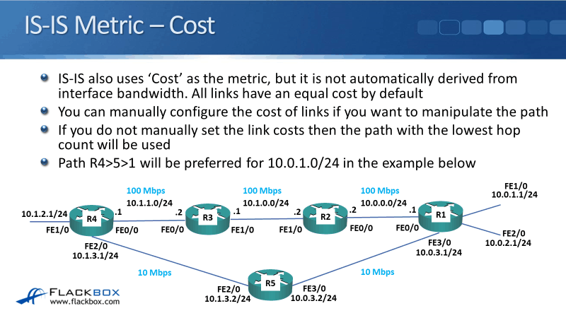
IS-IS also uses cost as the metric, but unlike with OSPF, it's not automatically derived from the interface bandwidth. All links have an equal cost by default.
If you want to force a particular path to be used in IS-IS based on which path has got the best bandwidth, you need to manually configure it to do so. It's not going to do it automatically as OSPF does.
If you don't manually set the link costs in IS-IS, the lowest hop count will be used. In our example, the traffic will pass through the bottom path, R4 to R5, to R1, by default. IS-IS can be manipulated so that the traffic will go along the top path, unlike RIP where you can’t manipulate such.
EIGRP Metric
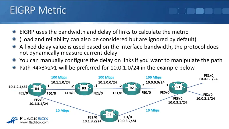
The last IGP we have is the EIGRP. It uses the bandwidth and delay of links to calculate the metric. Load and reliability can also be configured but they are ignored by default.
Bandwidth is used the same as it was with OSPF. EIGRP uses a fixed delay which is based on what the bandwidth is. You can also manually configure the delay on links if you want to manipulate the path.
OSPF and EIGRP use the best bandwidth links, therefore, they would typically choose the path that you would want to. But if for some reason it did not, you can override that with manual configuration. In our example, EIGRP will be going to use the top path by default because it has higher bandwidth links.
Choosing a Routing Protocol
Now, how would we choose a routing protocol? You do not want to be running multiple routing protocols inside your organization because it's going to get messy and it would make things hard to work with each other.
- Organizations would standardize on one protocol. The only reason they would have multiple different protocols is if there was a merger or there was some kind of historical or political reasons behind it.
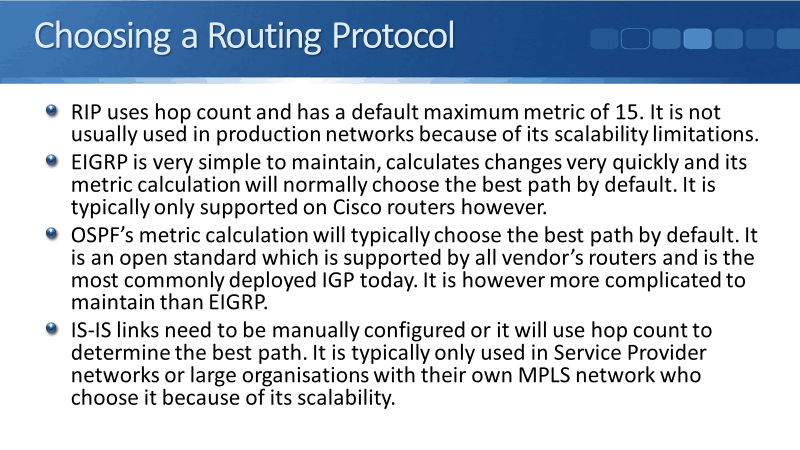
- RIP uses hop count and has a default maximum metric of 15. It's not usually used in production networks because of its scalability limitations.
- EIGRP is very simple to maintain, calculates changes very quickly, and its metric calculation will normally choose the best path by default. However, it is only supported on Cisco routers and was originally and completely Cisco proprietary.
Cisco made moves to open it up, but it's still mostly supported on Cisco routers. This kind of forces you into using all Cisco routers if you're going to use EIGRP.
- OSPF's metric calculation will choose the best path by default like EIGRP. It is an open standard that is supported by all vendors' routers, thus, making it the most commonly deployed IGP today. However, it is more complicated to maintain compared to EIGRP.
- IS-IS links need to be manually configured or else it will use hop count to determine the best path. IS-IS is typically used in service provider networks or in large organizations with their own MPLS network because of its scalability.
It comes down to either EIGRP or OSPF for most organizations. EIGRP is the simplest one to use and it works great, but you can really use it if you're using Cisco routers only. OSPF works great as well. It's more complicated to maintain though, however, it is supported on all vendors' routers.
Routing Protocol Metrics Configuration Example
This configuration example is taken from my free ‘Cisco CCNA Lab Guide’ which includes over 350 pages of lab exercises and full instructions to set up the lab for free on your laptop.
Click here to download your free Cisco CCNA Lab Guide.

-
- Enter the command below to remove OSPF on every router
no router ospf 1
2. Will R1 still have connectivity to R4?
Yes. RIP is still running so RIP routes will replace the removed OSPF routes in the routing table.
R1#show ip route
Codes: L - local, C - connected, S - static, R - RIP, M - mobile, B - BGP
D - EIGRP, EX - EIGRP external, O - OSPF, IA - OSPF inter area
N1 - OSPF NSSA external type 1, N2 - OSPF NSSA external type 2
E1 - OSPF external type 1, E2 - OSPF external type 2
i - IS-IS, su - IS-IS summary, L1 - IS-IS level-1, L2 - IS-IS level-2
ia - IS-IS inter area, * - candidate default, U - per-user static route
o - ODR, P - periodic downloaded static route, H - NHRP, l - LISP
+ - replicated route, % - next hop override
Gateway of last resort is not set
10.0.0.0/8 is variably subnetted, 10 subnets, 2 masks
C 10.0.1.0/24 is directly connected, FastEthernet0/1
L 10.0.1.1/32 is directly connected, FastEthernet0/1
C 10.0.2.0/24 is directly connected, FastEthernet1/0
L 10.0.2.1/32 is directly connected, FastEthernet1/0
C 10.0.3.0/24 is directly connected, FastEthernet1/1
L 10.0.3.1/32 is directly connected, FastEthernet1/1
R 10.1.0.0/24 [120/3] via 10.0.3.2, 00:00:12, FastEthernet1/1
R 10.1.1.0/24 [120/2] via 10.0.3.2, 00:00:12, FastEthernet1/1
R 10.1.2.0/24 [120/2] via 10.0.3.2, 00:00:12, FastEthernet1/1
R 10.1.3.0/24 [120/1] via 10.0.3.2, 00:00:12, FastEthernet1/1
3. What is the metric to the 10.1.1.0/24 network on R1?
A hop count of 2.
4. Why is there only one route on R1 to the 10.1.1.0/24 network now?
Interface FastEthernet 0/0 on R2 is still shut down so no routes go through it.
5. Make the required change so that there are two routes to the 10.1.1.0/24 network in the routing table on R1.
R2(config)#interface f0/0
R2(config-if)#no shut
R1#show ip route
Codes: L - local, C - connected, S - static, R - RIP, M - mobile, B - BGP
D - EIGRP, EX - EIGRP external, O - OSPF, IA - OSPF inter area
N1 - OSPF NSSA external type 1, N2 - OSPF NSSA external type 2
E1 - OSPF external type 1, E2 - OSPF external type 2, E - EGP
i - IS-IS, L1 - IS-IS level-1, L2 - IS-IS level-2, ia - IS-IS inter area
* - candidate default, U - per-user static route, o - ODR
P - periodic downloaded static route
Gateway of last resort is not set
10.0.0.0/8 is variably subnetted, 12 subnets, 2 masks
C 10.0.0.0/24 is directly connected, FastEthernet0/0
L 10.0.0.1/32 is directly connected, FastEthernet0/0
C 10.0.1.0/24 is directly connected, FastEthernet0/1
L 10.0.1.1/32 is directly connected, FastEthernet0/1
C 10.0.2.0/24 is directly connected, FastEthernet1/0
L 10.0.2.1/32 is directly connected, FastEthernet1/0
C 10.0.3.0/24 is directly connected, FastEthernet1/1
L 10.0.3.1/32 is directly connected, FastEthernet1/1
R 10.1.0.0/24 [120/1] via 10.0.0.2, 00:00:03, FastEthernet0/0
R 10.1.1.0/24 [120/2] via 10.0.3.2, 00:00:15, FastEthernet1/1
[120/2] via 10.0.0.2, 00:00:03, FastEthernet0/0
R 10.1.2.0/24 [120/2] via 10.0.3.2, 00:00:15, FastEthernet1/1
R 10.1.3.0/24 [120/1] via 10.0.3.2, 00:00:15, FastEthernet1/1
6. Enter the commands below on each router to provision a basic EIGRP configuration and enable EIGRP on every interface.
router eigrp 100
no auto-summary
network 10.0.0.0 0.255.255.255
7. What changes do you expect to see in the routing tables? Why?
The RIP routes will be replaced by EIGRP because its Administrative Distance of 90 is preferred to RIP’s AD of 120.
8. Verify the changes to the routing table on R1.
R1#show ip route
Codes: L - local, C - connected, S - static, R - RIP, M - mobile, B - BGP
D - EIGRP, EX - EIGRP external, O - OSPF, IA - OSPF inter area
N1 - OSPF NSSA external type 1, N2 - OSPF NSSA external type 2
E1 - OSPF external type 1, E2 - OSPF external type 2
i - IS-IS, su - IS-IS summary, L1 - IS-IS level-1, L2 - IS-IS level-2
ia - IS-IS inter area, * - candidate default, U - per-user static route
o - ODR, P - periodic downloaded static route, H - NHRP, l - LISP
+ - replicated route, % - next hop override
Gateway of last resort is not set
10.0.0.0/8 is variably subnetted, 12 subnets, 2 masks
C 10.0.0.0/24 is directly connected, FastEthernet0/0
L 10.0.0.1/32 is directly connected, FastEthernet0/0
C 10.0.1.0/24 is directly connected, FastEthernet0/1
L 10.0.1.1/32 is directly connected, FastEthernet0/1
C 10.0.2.0/24 is directly connected, FastEthernet1/0
L 10.0.2.1/32 is directly connected, FastEthernet1/0
C 10.0.3.0/24 is directly connected, FastEthernet1/1
L 10.0.3.1/32 is directly connected, FastEthernet1/1
D 10.1.0.0/24 [90/30720] via 10.0.0.2, 00:00:32, FastEthernet0/0
D 10.1.1.0/24 [90/33280] via 10.0.0.2, 00:00:29, FastEthernet0/0
D 10.1.2.0/24 [90/35840] via 10.0.0.2, 00:00:25, FastEthernet0/0
D 10.1.3.0/24 [90/261120] via 10.0.3.2, 00:00:19, FastEthernet1/1
9. What is the metric to the 10.1.1.0/24 network on R1?
A composite metric of 33280.
10. Why is there only one route to the 10.1.1.0/24 network on R1?
EIGRP uses a composite metric that takes into account interface bandwidth and delay. The interfaces on R5 have a configured bandwidth of 10Mbps. The interfaces along the top path of the network topology all have the default FastEthernet bandwidth of 100Mbps so this route is preferred. All traffic will go via the next hop 10.0.0.2.
11. Disable RIP and EIGRP on R5 with the commands below.
R5(config)#no router rip
R5(config)#no router eigrp 100
12. Configure the network so that there is still connectivity between all subnets if the link between R1 and R2 goes down. Accomplish this with six commands. Do not enable EIGRP on R5 but note that the routing protocol is expected to be enabled there in the future.
Floating static routes need to be added as a backup to the EIGRP routes. We want to ensure EIGRP routes are preferred when available so set the AD to be higher than EIGRP’s AD of 90.
R1(config)#ip route 10.1.0.0 255.255.0.0 10.0.3.2 95
R2(config)#ip route 10.0.0.0 255.255.0.0 10.1.0.1 95
R3(config)#ip route 10.0.0.0 255.255.0.0 10.1.1.1 95
R4(config)#ip route 10.0.0.0 255.255.0.0 10.1.3.2 95
R5(config)#ip route 10.0.0.0 255.255.0.0 10.0.3.1 95
R5(config)#ip route 10.1.0.0 255.255.0.0 10.1.3.1 95
R5 is not running EIGRP so it is not currently necessary to set the Administrative Distance for its routes to 95. It is required to prevent the floating static routes from being preferred when EIGRP is enabled in the future however, summary routes need to be used to accomplish the task in six commands.
13. What changes do you expect to see to the routing table on R1?
The summary route will be added to the routing table but not used because it has a prefix length of /16, compared to the EIGRP routes which have a longer prefix length of /24.
If individual floating static routes had been added for each of the /24 destination networks then these would not have appeared in the routing table (unless a link went down) because EIGRP has a better Administrative Distance.
14. Verify the changes to the routing table on R1.
R1#sh ip route
Codes: L - local, C - connected, S - static, R - RIP, M - mobile, B - BGP
D - EIGRP, EX - EIGRP external, O - OSPF, IA - OSPF inter area
N1 - OSPF NSSA external type 1, N2 - OSPF NSSA external type 2
E1 - OSPF external type 1, E2 - OSPF external type 2
i - IS-IS, su - IS-IS summary, L1 - IS-IS level-1, L2 - IS-IS level-2
ia - IS-IS inter area, * - candidate default, U - per-user static route
o - ODR, P - periodic downloaded static route, H - NHRP, l - LISP
+ - replicated route, % - next hop override
Gateway of last resort is not set
10.0.0.0/8 is variably subnetted, 13 subnets, 3 masks
C 10.0.0.0/24 is directly connected, FastEthernet0/0
L 10.0.0.1/32 is directly connected, FastEthernet0/0
C 10.0.1.0/24 is directly connected, FastEthernet0/1
L 10.0.1.1/32 is directly connected, FastEthernet0/1
C 10.0.2.0/24 is directly connected, FastEthernet1/0
L 10.0.2.1/32 is directly connected, FastEthernet1/0
C 10.0.3.0/24 is directly connected, FastEthernet1/1
L 10.0.3.1/32 is directly connected, FastEthernet1/1
S 10.1.0.0/16 [95/0] via 10.0.3.2
D 10.1.0.0/24 [90/30720] via 10.0.0.2, 00:04:48, FastEthernet0/0
D 10.1.1.0/24 [90/33280] via 10.0.0.2, 00:04:45, FastEthernet0/0
D 10.1.2.0/24 [90/35840] via 10.0.0.2, 00:04:41, FastEthernet0/0
D 10.1.3.0/24 [90/266240] via 10.0.0.2, 00:03:02, FastEthernet0/0
15. Verify that traffic from PC1 to PC3 still goes via R2.
C:\>tracert 10.1.2.10
Tracing route to 10.1.2.10 over a maximum of 30 hops:
1 1 ms 0 ms 1 ms 10.0.1.1
2 0 ms 3 ms 0 ms 10.0.0.2
3 1 ms 0 ms 0 ms 10.1.0.1
4 0 ms 1 ms 0 ms 10.1.1.1
5 * 0 ms 0 ms 10.1.2.10
Trace complete.
16. Shut down interface FastEthernet 0/0 on R2.
R2(config)#interface f0/0
R2(config-if)#shutdown
17. What changes do you expect to see on R1’s routing table?
The EIGRP routes will be removed.
18. Verify the changes to the routing table on R1.
R1#show ip route
Codes: L - local, C - connected, S - static, R - RIP, M - mobile, B - BGP
D - EIGRP, EX - EIGRP external, O - OSPF, IA - OSPF inter area
N1 - OSPF NSSA external type 1, N2 - OSPF NSSA external type 2
E1 - OSPF external type 1, E2 - OSPF external type 2
i - IS-IS, su - IS-IS summary, L1 - IS-IS level-1, L2 - IS-IS level-2
ia - IS-IS inter area, * - candidate default, U - per-user static route
o - ODR, P - periodic downloaded static route, H - NHRP, l - LISP
+ - replicated route, % - next hop override
Gateway of last resort is not set
10.0.0.0/8 is variably subnetted, 7 subnets, 3 masks
C 10.0.1.0/24 is directly connected, FastEthernet0/1
L 10.0.1.1/32 is directly connected, FastEthernet0/1
C 10.0.2.0/24 is directly connected, FastEthernet1/0
L 10.0.2.1/32 is directly connected, FastEthernet1/0
C 10.0.3.0/24 is directly connected, FastEthernet1/1
L 10.0.3.1/32 is directly connected, FastEthernet1/1
S 10.1.0.0/16 [95/0] via 10.0.3.2
19. Verify connectivity between PC1 and PC3.
C:\>ping 10.1.2.10
Pinging 10.1.2.10 with 32 bytes of data:
Reply from 10.1.2.10: bytes=32 time=1ms TTL=125
Reply from 10.1.2.10: bytes=32 time=1ms TTL=125
Reply from 10.1.2.10: bytes=32 time=1ms TTL=125
Reply from 10.1.2.10: bytes=32 time<1ms TTL=125
Ping statistics for 10.1.2.10:
Packets: Sent = 4, Received = 4, Lost = 0 (0% loss),
Approximate round trip times in milli-seconds:
Minimum = 0ms, Maximum = 1ms, Average = 0ms
21. Verify the traffic goes via R5.
C:\>tracert 10.1.2.10
Tracing route to 10.1.2.10 over a maximum of 30 hops:
1 0 ms 0 ms 1 ms 10.0.1.1
2 0 ms 0 ms 0 ms 10.0.3.2
3 0 ms 0 ms 0 ms 10.1.3.1
4 0 ms 0 ms 1 ms 10.1.2.10
Trace complete.
22. Bring interface FastEthernet 0/0 on R2 back up.
R2(config)#interface f0/0
R2(config-if)#no shutdown
23. Enter the commands below on R5 to provision a basic EIGRP configuration and enable EIGRP on every interface.
R5(config)#router eigrp 100
R5(config-router)#no auto-summary
R5(config-router)#network 10.0.0.0 0.255.255.255
Additional Resources
Cisco Networking Academy's Introduction to Routing Dynamically: http://www.ciscopress.com/articles/article.asp?p=2180210&seqNum=7
Configure Route Selection for Routers: https://www.cisco.com/c/en/us/support/docs/ip/enhanced-interior-gateway-routing-protocol-eigrp/8651-21.html
Administrative Distance & Metric: https://study-ccna.com/administrative-distance-metric/
Libby Teofilo

Text by Libby Teofilo, Technical Writer at www.flackbox.com
Libby’s passion for technology drives her to constantly learn and share her insights. When she’s not immersed in the tech world, she’s either lost in a good book with a cup of coffee or out exploring on her next adventure. Always curious, always inspired.