In this Cisco CCNA tutorial, you’ll learn about the OSPF Designated Router (DR) and Backup Designated Router (BDR) designated routers. Scroll down for the video and also text tutorials.
Cisco OSPF DR and BDR Designated Routers Video Tutorial

Nassim Bouchama

I took your course and made a promise from the first video, “the day I succeed I will tell you.” I passed my CCNA today, my score was 976/1000. I’m very happy and would to thank you for your support!
OSPF on Multiaccess Segments
When you enable OSPF on a router's interface, the router will send Hello packets out of that interface, trying to discover other OSPF routers that can form an adjacency. When two OSPF routers on the same link send Hello packets to each other, they will first off move into the two-way state, where they've discovered each other.
They will then move into the exchange state, where they will agree to exchange routing updates with each other, and will then move through loading, where they're exchanging the updates. Finally, they'll be at the full state where they are fully adjacent and they've shared all of their routing information with each other
On point-to-point links, OSPF router pairs will always form a full adjacency. There are only two routers on point-to-point links, so of course, they're going to want to share their full information with each other.
But on multiaccess segments such as Ethernet, where there can be multiple routers, it's inefficient for all routers to form a full OSPF adjacency with each other. If you look at the example below, you can see there's an Ethernet segment. All 4 routers are plugged into the switch, and on their interfaces connected to that switch, they're all in the same IP subnet.
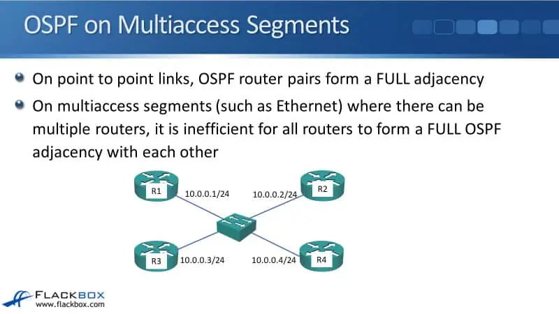
The IP addresses are:
- R1 - 10.0.0.1/24
- R2 - 10.0.0.2/24
- R3 - 10.0.0.3/24
- R4 - 10.0.0.4/24
In the example, they've all got OSPF enabled on their interfaces, so they're going to be sharing OSPF information out on the links. That would be inefficient if the topology was a full mesh. They would all be sharing the full information with each other, and there would be a lot of repetitive information being sent out to the same link.
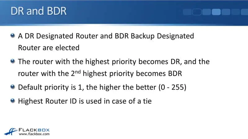
DR and BDR
So, a better idea would be if one of these routers could be elected as a master, and then all the routers could share the information with it, and then it could reflect that information out to the other routers. Rather than having a full mesh, they just send the information to the master, and it's up to the master to reflect it out.
The master is called the Designated Router (DR). There would be a problem if the master or DR goes down. Particularly if a router has just sent an update to the DR and then the DR was down before it could send the update to the other routers. The information would be lost.
Because of that, we want to have some redundancy here. We're also going to have a Backup Designated Router (BDR), just in case the DR goes down.
The DR and the BDR are elected on each multiaccess segment. In the topology earlier, you can see all of the routers got an interface connected to the same multiaccess segment. The DR and the BDR act at the interface level, not at the entire router level.
For example, R1 had another interface which was also connected to an Ethernet segment. That separate segment would also have its own DR and BDR elected.
The router with the highest priority becomes the DR, and the router with the second highest priority becomes the BDR. The default priority on the routers is 1, and the higher the number, the better, the more preferred. The possible values are 0 to 255, with 255 being the best possible value.
If you configure a value of 0, that means that that router will never be the Designated Router. The highest router ID is used in the case of a tie. So, if you don't explicitly set the priority, all the routers on the link are going to have the same priority of 1, and the one that is going to be elected as the DR is the one with the highest router ID.
In the real world, that is what will typically happen. If you've got routers that are connected to the same link, they're probably going to be very similar models of routers anyway. This just really does not put a lot of loads on routers, so normally, you're not going to really care which one is the DR.
You need to understand how this works so that if you do have problems, you can troubleshoot it. But as far as configuring anything, typically, in the real world, you'll just leave the routers to figure it out themselves as to which one is going to be the DR.
In the CCNA exam, you might be asked to configure one as the DR though, so you need to understand how this works, and you need to know how to configure priority as well.
Neighbor States – 2-Way
On multiaccess segments such as the Ethernet, the routers elect the DR and BDR at the 2-way stage. When the routers did not discover each other yet, the OSPF state is down. They then send Hellos when they discover each other through the Hello messages, and then they move to the 2-way stage.
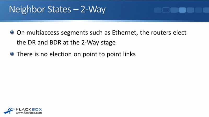
At the 2-way stage, they have not started exchanging any routing information yet. They then move through the exchange, the loading, and the full states. The DR and the BDR election happen at the 2-way stage before the routing information has been exchanged.
We don't want all the routers exchanging the full information with each other, just with the DR and the BDR. So, we need to have this set up before routing information is exchanged between the routers.
Now, the election just happens on multiaccess segments. The router knows if that interface is an Ethernet interface, so it knows that there needs to be a DR elected there. Let's say there's a Serial interface with a point-to-point link there. The router knows that is a point-to-point link, and there will be no DR to be elected on that link.
Setting OSPF Priority
If we do want to manually set which of the routers is the DR, we use the command
interface FastEthernet 0/0
ip ospf priority 100
As long as you set it to more than 1, it will be the preferred router. If you wanted to configure a DR and a BDR, you could configure the DR with 100 and the BDR with 50, for example. The DR will have a higher priority value compared to the BDR.
If you want to specify that a router will not become a DR, then you can enter this command on the interface:
ip ospf priority 0
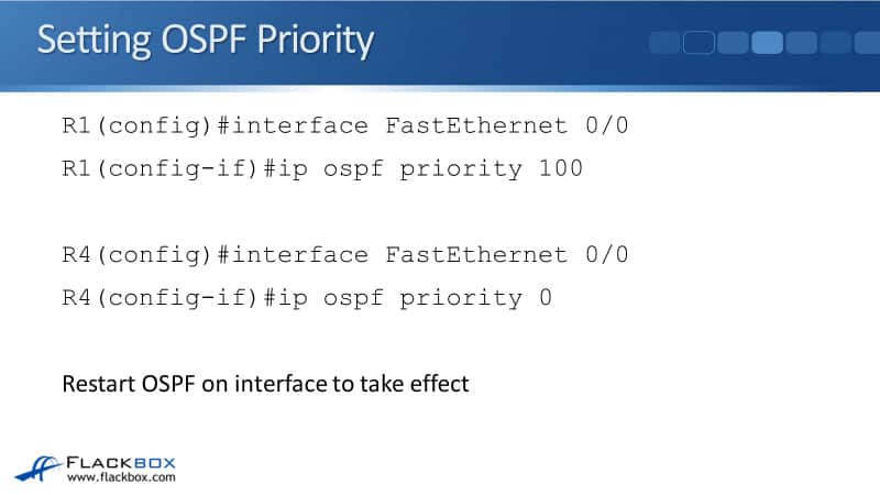
After you've configured this command on the interface, it's not going to take effect yet until OSPF has been restarted on that interface. You can do any of the following to restart OSPF:
- Reboot the router
- Shut down the interface and bring it back up again
- Enter this command on the enable prompt: clear ip ospf
Obviously, all of these would be disruptive, so be careful if you're going to do it in a production environment.
Multiaccess Segment Neighbor States
The DR and BDR establish a full neighbor state with all routers on the network segment. The neighbor state of other routers remains in a two-way state and they do not directly exchange routes with each other.
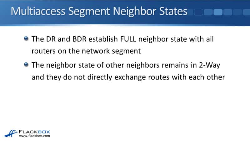
For example, on the example topology we had earlier, let's say that R1 is the DR and R2 is the BDR. R1 and R2 will go to the full state with all of the other routers. R3 and R4 will go to the full state with R1 and R2 because those are the Designated Routers.
But if you look at the state between R3 and R4, they will just be in the two-way state with each other because neither of them is a DR. Routers that are not DRs will just have a two-way relationship with each other.
They're not exchanging full routing information directly with each other. However, R3 and R4 will still learn each other's routes, because that will be reflected down from the DR.
Multiaccess Segment LSA Updates
When a link state changes on a router, if a new link comes up or if a link goes down and that's connected to a multiaccess segment, it sends a multicast Link State Update (LSU) packet to 224.0.0.6, which is the multicast address for all Designated Routers.

It's just the DR and the BDR that are listening in for packets that are sent to that address. With our example, if any of the routers, R1, R2, R3, or R4, sees a link state change, it will send an update about that to 224.0.0.6, and both the DR and the BDR will learn about that change.
Then, the DR multicasts the update. So when there are any changes, it will be sent to the DR and the BDR. The DR then sends that out to the other routers on the link. In that case, if there's any change anywhere, all the routers on the link will still learn about it.
Cisco OSPF DR and BDR Designated Routers Configuration Example
This configuration example is taken from my free ‘Cisco CCNA Lab Guide’ which includes over 350 pages of lab exercises and full instructions to set up the lab for free on your laptop.
Click here to download your free Cisco CCNA Lab Guide.

1. Enable a loopback interface on routers R6 to R9. Use the IP address 192.168.0.x/32, where ‘x’ is the router number. For example 192.168.0.6/32 on R6.
On routers R6 to R9:
R6(config)#interface loopback0
R6(config-if)#ip address 192.168.0.6 255.255.255.255
2. Enable OSPF for Area 0 on the Loopback 0 and FastEthernet 0/0 interfaces on routers R6 to R9.
On routers R6 to R9:
R6(config)#router ospf 1
R6(config-router)#network 172.16.0.0 0.0.0.255 area 0
R6(config-router)# network 192.168.0.0 0.0.0.255 area 0
You can use different network statements, as long as they cover the range of IP addresses configured on the router interfaces.
3. Set the reference bandwidth on routers R6 to R9 so that a 100 Gbps interface will have a cost of 1.
Remember to do this on all routers R6 to R9.
R6(config)#router ospf 1
R6(config-router)#auto-cost reference-bandwidth 100000
4. Which routers do you expect to be the DR and BDR on the Ethernet segment? Verify this.
OSPF priority has not been set so all routers will have the default of 1.
R9 and R8 will be elected as the DR and BDR respectively because the have the highest Router IDs (because they have the highest IP addresses on their loopback interfaces).
R6#show ip ospf interface FastEthernet 0/0
FastEthernet0/0 is up, line protocol is up
Internet address is 172.16.0.6/24, Area 0
Process ID 1, Router ID 192.168.0.6, Network Type BROADCAST, Cost: 1000
Transmit Delay is 1 sec, State DROTHER, Priority 1
Designated Router (ID) 192.168.0.9, Interface address 172.16.0.9
Backup Designated Router (ID) 192.168.0.8, Interface address 172.16.0.8
R6#show ip ospf neighbor
Neighbor ID Pri State Dead Time Address Interface
192.168.0.8 1 FULL/BDR 00:00:31 172.16.0.8 FastEthernet0/0
192.168.0.7 1 2WAY/DROTHER 00:00:39 172.16.0.7 FastEthernet0/0
192.168.0.9 1 FULL/DR 00:00:39 172.16.0.9 FastEthernet0/0
R9#show ip ospf neighbor
Neighbor ID Pri State Dead Time Address Interface
192.168.0.8 1 FULL/BDR 00:00:31 172.16.0.8 FastEthernet0/0
192.168.0.7 1 2WAY/DROTHER 00:00:39 172.16.0.7 FastEthernet0/0
192.168.0.6 1 FULL/DROTHER 00:00:39 172.16.0.6 FastEthernet0/0
5. Set R6 as the Designated Router without changing any IP addresses.
Configure a higher OSPF priority on R6.
R6(config)#interface FastEthernet0/0
R6(config-if)#ip ospf priority 100
R6(config-if)#end
R6#clear ip ospf process
6. Verify R6 is the Designated Router.
R6#show ip ospf interface FastEthernet 0/0
FastEthernet0/0 is up, line protocol is up
Internet address is 172.16.0.6/24, Area 0
Process ID 1, Router ID 192.168.0.6, Network Type BROADCAST, Cost: 1000
Transmit Delay is 1 sec, State DR, Priority 100
Designated Router (ID) 192.168.0.6, Interface address 172.16.0.6
Backup Designated Router (ID) 192.168.0.8, Interface address 172.16.0.8
R6#show ip ospf neighbor
Neighbor ID Pri State Dead Time Address Interface
192.168.0.8 1 FULL/BDR 00:00:31 172.16.0.8 FastEthernet0/0
192.168.0.7 1 2WAY/DROTHER 00:00:39 172.16.0.7 FastEthernet0/0
192.168.0.9 1 FULL/DROTHER 00:00:39 172.16.0.9 FastEthernet0/0
R9#show ip ospf neighbor
Neighbor ID Pri State Dead Time Address Interface
192.168.0.8 1 FULL/BDR 00:00:31 172.16.0.8 FastEthernet0/0
192.168.0.7 1 2WAY/DROTHER 00:00:39 172.16.0.7 FastEthernet0/0
192.168.0.6 100 FULL/DR 00:00:39 172.16.0.6 FastEthernet0/0
Additional Resources
Understand OSPF Neighbor States: https://www.cisco.com/c/en/us/support/docs/ip/open-shortest-path-first-ospf/13685-13.html
OSPF Designated Router (DR) and Backup Designated Router (BDR): https://study-ccna.com/designated-backup-designated-router/
Cisco OSPF Basic Configuration: https://www.flackbox.com/cisco-ospf-basic-configuration
Libby Teofilo

Text by Libby Teofilo, Technical Writer at www.flackbox.com
Libby’s passion for technology drives her to constantly learn and share her insights. When she’s not immersed in the tech world, she’s either lost in a good book with a cup of coffee or out exploring on her next adventure. Always curious, always inspired.