In this Cisco CCNA tutorial, we’re going to cover Layer 3 of the OSI model, which is the Network Layer. Scroll down for the video and also the text tutorials.
The Cisco IP Header Video Tutorial
Abdulai Fadiga

I had studied many courses before and failed the CCNA exam twice.
I found your course and quickly realized that it was designed to help candidates not only pass the exam, but also to help them understand how networks functions in the real world and serve as a reference for any real-world projects.
Five weeks later, after thoroughly studying your course, I was able to pass the CCNA exam.
I am now a Technical Consultant at a telecommunication service provider here in West Africa.
Layer 3 – The Network Layer
The Network Layer is responsible for routing packets to their destination on the network, so this is why routers operate at the Network Layer, and it’s also responsible for Quality of Service (QoS).
For Quality of Service, you might have one particular type of traffic that requires a better level of service than another level of traffic. For example, if you’re running voice or video over IP. It’s sensitive to delay, so we’re going to give it better Quality of Service than something like email.
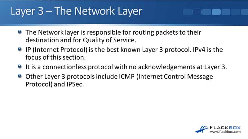
Internet Protocol (IP) is the best-known Layer 3 protocol. There’s IPv6 as well, which is the upgrade for IPv4. IP is a connectionless protocol, so there are no acknowledgments at Layer 3. You can still have reliable traffic by using TCP and its acknowledgments at Layer 4 or building it into the upper layers.
Other Layer 3 protocols apart from IP include ICMP, the Internet Control Message Protocol, which is used for ping and troubleshooting, and IPSec for secure encrypted communications. There are other protocols as well, but IP is the best-known one, by far the most commonly used.
IP Addressing
IP addressing is a logical addressing scheme that is implemented at Layer 3. The network designer uses IP addressing to partition the overall network into smaller subnetworks, commonly called subnets. Having different subnets improves performance and security and makes troubleshooting easier.
It improves performance because rather than having one big flat network, we divide it into smaller subnets, and we can keep the traffic on the particular subnet that it needs to be on rather than going everywhere. So, we get better performance that way.
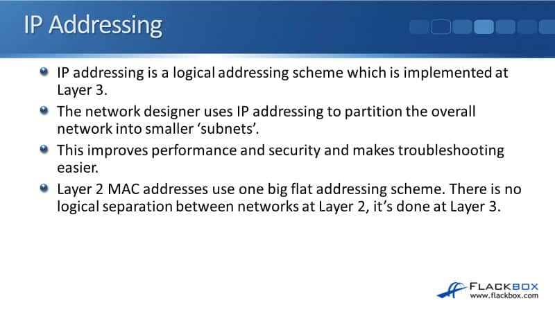
We also get better security by having this logical addressing as well. For example, let’s say that we’ve got accounting servers. We can put them on one particular subnet, which makes it really easy to control who has access to those servers.
Also, it makes troubleshooting easier because by partitioning the network in o smaller parts, if we have a problem, it’s easy to see what part of the network the problem is on and concentrate there. Layer 3 addressing uses IP addresses. At Layer 2, we have MAC addresses if we’re using Ethernet.
- Layer 3 (Network): IP Address
- Layer 2 (Data Link): MAC Address
IP addresses a logical addressing scheme. MAC addresses are just one big flat global addressing scheme. Moreover, there’s no logical separation in the Layer 2 OSI model. It’s done at Layer 3 with IP addressing.
OSI Reference Model - Encapsulation
As usual, we’ll have a review of the OSI stack again. You’re going to see this several times because it’s important, and I really want to drill into you about how networking works based on the OSI model.
We’ve got the seven layers. The top 3 Layers are the upper layers, mainly the concern of application developers. Layer 7 is the Application Layer, where when a sender is going to send traffic, it composes the packet.
It creates the Layer 7 information first. That then gets encapsulated in the Layer 6 Presentation Layer header, then encapsulated in the Session Layer header.
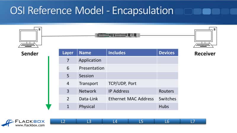
As networkers, we start getting interested at Layer 4, so the packet we’ve got from Layers 7, 6, 5 then gets encapsulated with the Layer 4 header, which will either be a TCP or a UDP header, and the port information will be on there. That then gets further encapsulated in the Layer 3 header.
The main information in the Layer 3 header is the IP address information that you’ll see coming up shortly with the rest of the information in the header. The network infrastructure device that works at Layer 3 is our routers.
Then, we carry on making the packet we put onto the Layer 2 header, the Data-Link header, on a Local Area Network (LAN) using Ethernet, and we’ll have the source and destination MAC address there. The network devices that work at Layer 2 are our switches. Finally, the packet will actually get put onto the physical wire at the Physical Layer. The hubs work at the Physical Layer.
The IP Header
Now, we’re going to take a look at the IP header. In the top row that you see there, the first part is a 4-bit version. It’s either IPv4 or IPv6 that’s referenced in that field. We then have the 4-bit header length, the length of the IP header.
We then have the type of service byte used for Quality of Service information. So we can put a marking on the packet to specify what kind of traffic this is, and on our routers later, we can take an action based on that marking to give it better service if we need to, for example, for our Voice over IP (VOIP) traffic.
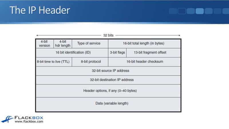
We then have the 16-bit total length of the packet. The next row underneath is used for fragment information. With our different media types, for example, Ethernet, there is a maximum transmission unit size, the maximum size of the packet.
The maximum size by default in Ethernet is a 1500 byte MTU. If we try a packet onto the wire that is larger than that size, it has to get split up into smaller parts called fragments.
The second row of information on the IP header is used to help keep track of those fragments. In the next row down, we have an 8-bit time to live (TTL) field. Every time a packet goes through a router, the router will decrement the TTL field by one.
If it gets down to zero, that router will drop the packet, preventing routing loops. We might have an error in our network somewhere that is causing packets to endlessly loop around the network without ever getting to their destination. We don’t want packets to loop around forever, so TTL will prevent that and drop them.
Now, it doesn’t fix the underlying problem. We still need to cure the loop. Once the traffic gets there, that stops us from having a huge amount of traffic built up on the network, slowing it down, which is just looping.
The next field, the 8-bit protocol, will specify the Layer 4 information type, typically TCP or UDP. We then have a checksum to check that packet has not been corrupted in transit.
Next, we have the source IP address specifying where the packet came from and the destination IP address specifying where the packet is going. The next field is the header options, where we can put in additional information, it’s not commonly used. Finally, we have the data, the rest of the packet.
Additional Resources
Internet Addressing and Routing First Step: https://www.ciscopress.com/articles/article.asp?p=348253&seqNum=4
IPv4 Packet Header: https://networklessons.com/cisco/ccna-routing-switching-icnd1-100-105/ipv4-packet-header
IP Header: https://study-ccna.com/ip-header/
Libby Teofilo

Text by Libby Teofilo, Technical Writer at www.flackbox.com
Libby’s passion for technology drives her to constantly learn and share her insights. When she’s not immersed in the tech world, she’s either lost in a good book with a cup of coffee or out exploring on her next adventure. Always curious, always inspired.