In this Cisco CCNA training tutorial, you’ll learn how to configure BGP (the Border Gateway Protocol) neighbors in a Service Provider environment. Scroll down for the video and also text tutorial.
This is the 3rd in a series of BGP tutorials.
Part 1: Why We Need BGP
Part 2: BGP Routing and Path Selection for Service Providers
Part 4: How to Advertise BGP Routes on Cisco Routers
Part 5: Cisco BGP for Enterprises
Configuring BGP Neighbors on Cisco Routers Video Tutorial
Krystian Krupinski

I want to let you know that I passed my CCNA. I’m really happy with my achievement and it’s all thanks to you! Your course is by far the best one out there.
BGP Neighbors Lab Example
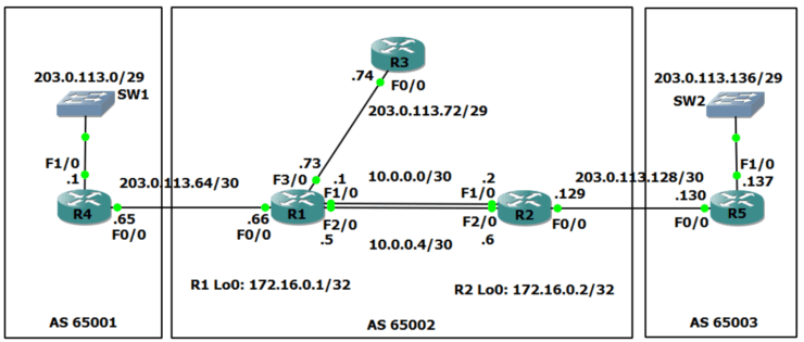
We'll walk through an example scenario, using the topology shown in the diagram below.

BGP AS (Autonomous System) 65001 is on the left, AS 65002 is in the middle, and AS 65003 is on the right. Each AS is owned and managed by a separate Internet Service Provider. In the scenario, we are the Service Provider in the middle with AS65002.
R1 and R2 are our own internal routers. R3 belongs to a customer who are using us as their Service Provider.
BGP is used for routing between different Autonomous Systems. Each AS also needs to run an Interior Gateway Protocol (IGP) such as OSPF or ISIS for routing within the AS.
In the scenario OSPF has already been configured as our IGP on our routers R1 and R2.
R1 and R2 also have a route to the 203.0.113.72/29 range of public IP addresses bought by our customer with the R3 router.
We need to have connectivity between all of the public IP addresses everywhere. The Service Provider on the left has already configured an IGP and BGP for AS 65001, and the Service Provider on the right has already done the same for AS 65003. We need to do the BGP configuration for AS 65002.
iBGP and eBGP
When you're configuring BGP internally between your own routers it's called ‘iBGP’ (internal BGP). When you configure BGP to another AS, that's ‘eBGP’ (external BGP).
We're going to configure iBGP between our two routers, R1 and R2, and we're going to also configure eBGP from R1 to R4 and R2 to R5.
There are some different rules for how iBGP and eBGP behave, but they're both part of the same BGP routing process and routes are shared between both iBGP and eBGP neighbors. The differences between iBGP and eBGP are not important in this CCNA level tutorial, but if you go on to do CCNA Service Provider or take BGP at the CCNP level you'll learn about them then.
The BGP Neighbor Command (BGP doesn't use Link-Local Multicast Hellos like an IGP)
The first thing to configure is the ‘neighbor’ command. Peering between routers works differently for BGP than it does for IGPs. BGP routers within an AS are often not directly physically connected, they can be multiple hops away from each other. So unlike in IGPs, link-local multicast Hello messages cannot be used to form adjacencies.
Link-local multicast means when the packet is received on a router’s interface, the router will not forward it on out another interface. For a router to receive a link-local multicast packet, it must be connected to the same Layer 2 network (‘Layer 2 adjacent’) as the sending router (eg the two routers are directly connected or there is just a switch between them, there is not another router between them.)
For routers which are running an IGP to discover each other and form an adjacency we enable the IGP at the router interface level. The router then sends out multicast link-local Hellos on that interface, and if there is another Layer 2 adjacent router using the same routing protocol then they will discover each other, form an adjacency and start sharing routing information.
Link-local multicast is perfect for IGPs where each router has Layer 2 adjacency with one or more other routers configured with the same routing protocol. This allows Layer 2 adjacent routers to discover each other and form routing protocol adjacencies with each other. Once all routers are known by the IGP then internal connectivity is established throughout the AS.
Link-local multicast is not however suitable for BGP because the neighbors are often multiple router hops apart. You have to manually specify the BGP neighbors.
BGP Neighbor Configuration
You use a ‘neighbor’ statement and you specify the IP address of the other router that you want this router to peer with. Targeted unicast TCP sessions using TCP port 179 are used to establish the peering and also to exchange routes once the peering has been done.
There must be a route to the neighbor IP address in this router's routing table or it won’t know how to send the BGP packet to the destination router. (This is one of the first things to check when troubleshooting BGP peering issues.)
You can see an example below where we’ve configured R1 with a neighbor statement for R3:
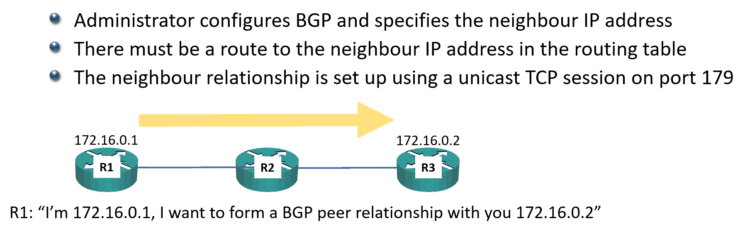
R1 has IP address 172.16.0.1, it’s desired BGP neighbor R3 has IP address 172.16.0.2, and there's R2 in between the middle of them. We configure R1 to say that we want it to form a BGP peering with 172.16.0.2.
At global configuration mode we enter the configuration for BGP and specify our AS number:
R1(config)#router bgp 65002
Then we configure the neighbor statement with the IP address of the other BGP router, and specify the AS that other router is in. (This is how the router knows whether it is an iBGP or eBGP neighbor. If the remote AS matches our AS, as in this case, it’s an iBGP neighbor.)
R1(config-router)#neighbor 172.16.0.2 remote-as 65002
R1 will send the BGP request out as TCP unicast traffic. It says, "I'm 172.16.0.1" and that it wants to form a BGP relationship with 172.16.0.2.
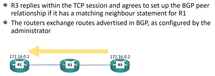
R3 will reply within that TCP session and it will agree to set up the BGP peer relationship if it has a matching neighbor statement for R1:
R3(config)#router bgp 65002
R3(config-router)#neighbor 172.16.0.2 remote-as 65002
When that is done, the routers will then exchange routes that are advertised in BGP, as configured by you the administrator (we’ll cover how to do that in the next post.)
Using Loopback Addresses in BGP Neighbor statements
Our iBGP neighbors can be multiple physical hops apart and/or have multiple redundant paths to reach each other.
If the IP address of a physical interface is used for the BGP session and that physical interface goes down then so will the BGP session, even though there is an alternative path to the other BGP router. If that doesn't make sense yet, you'll see it in the next diagram coming up.
Loopback addresses (which are advertised in the IGP) are typically used as the address in the BGP neighbor statement because of this. This way, BGP peers can continue to reach each other even if a physical interface goes down.
Let’s have a look at how that works. In the diagram below, we're going to form a BGP relationship between the R1 and R2 routers.
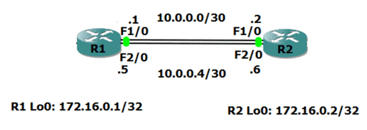
There's redundant (backup) links between the two routers. We’re using the 10.0.0.0/30 network on the link at the top, and the 10.0.0.4/30 network on the bottom.
From R1, when we configure the BGP neighbor statement pointing at R2, we could say we want to peer with 10.0.0.2 along the top path. But if we do that and that link goes down, then the BGP relationship is going to go down as well, even though R1 still has connectivity to R2 along the bottom path at 10.0.0.6.
Obviously, if we point at 10.0.0.6, we've got the same problem. If that bottom path goes down, BGP also goes down, even though we can get to the router along the top path.
Best practice is to use loopback addresses for iBGP neigbors, even if there is not a redundant path between them – we don’t want to have to reconfigure if one is added later.
The configuration for our example above:
R1(config)#router bgp 65002
R1(config-router)#neighbor 172.16.0.2 remote-as 65002
R2(config)#router bgp 65002
R2(config-router)#neighbor 172.16.0.1 remote-as 65002
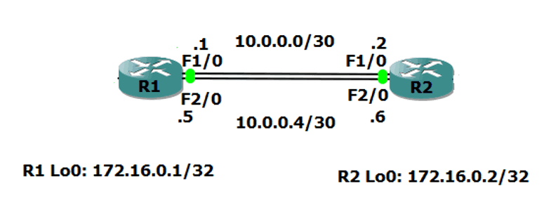
The BGP Update-Source Command
Using loopback addresses for our neighbor statements leads to a common gotcha with BGP. BGP has a security mechanism where it will only peer with another router if it has a matching neighbor statement for that peer. The source address in the packets received from the neighbor must match the exact IP address in the neighbor statement on this router.
When a router sends packets from itself, it uses the IP address of the exit interface as the source address by default.
This is not just for BGP. This is for all traffic. If you send a ping from the command line on the router, the source address will be the address of the interface that the packet goes out of. This is going to cause BGP peering to fail between loopback addresses if we don't do something about it.
Let’s see why…
R1(config)#router bgp 65002
R1(config-router)#neighbor 172.16.0.2 remote-as 65002
R2(config)#router bgp 65002
R2(config-router)#neighbor 172.16.0.1 remote-as 65002
On R1, we point it at the neighbor of 172.16.0.2. On R2, we've got a neighbor statement for 172.16.0.1.
When R1 sends the BGP packet out to R2, it's load balanced and is either going to go along the top path or the bottom path. If it goes along the top path, it goes out interface FastEthernet 1/0 with IP address 10.0.0.1. That packet will be sent with a source address of 10.0.0.1.
When it reaches R2, R2 sees that another router is trying to form a BGP relationship with it. R2 checks to see if it has a matching BGP neighbor statement. R2 has a neighbor statement for 172.16.0.1, but it does not have a neighbor statement for 10.0.0.1 so the BGP peering will be rejected.
R2 is not smart enough to realise it's the same router, just using a different IP address. The IP address has to match exactly.
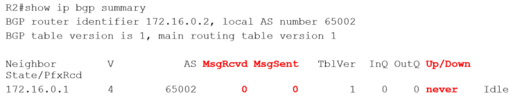
The ‘show ip bgp summary’ command will show whether the neighbor BGP peering succeeded or not. Here we can see there's been no messages sent or received and it's never come up.
What we have to do is tell R1 and R2, "When you send that BGP traffic to each other, use your loopback address rather than the address that's on the exit interface."
We do this by adding an additional command an additional command to the BGP configuration to specify the source IP address that we want to use. This overrides the default of using the IP address of the exit interface.
R1(config)#router bgp 65002
R1(config-router)#neighbor 172.16.0.2 remote-as 65002
R1(config-router)#neighbor 172.16.0.2 update-source loopback 0
R2(config)#router bgp 65002
R2(config-router)#neighbor 172.16.0.1 remote-as 65002
R2(config-router)#neighbor 172.16.0.1 update-source loopback 0
Now when R1 sends BGP traffic to R2 it uses a source address of 172.16.0.1, which matches the BGP neighbor statement on R2. And when R2 sends BGP traffic to R1 it uses a source address of 172.16.0.2, which matches the BGP neighbor statement on R1. Everything ties up on both sides so BGP peering will come up successfully.
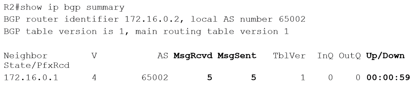
We can see that there are being messages sent and received, and it's been up for nearly a minute. So that is all good now.
BGP Neighbor Verification
Notice the verification is a little bit different than with our IGPs. After we’ve configured OSPF, normally the first thing we'll do is a ‘show IP OSPF neighbor’ and for EIGRP we'll do a ‘show IP EIGRP neighbor’. That will show us a short summary of the neighbors and whether they're up or not.
But in BGP, we don't use ‘show IP BGP neighbor’ to get a summary, we use ‘show IP BGP summary’.
‘show IP BGP neighbors’ is a valid command as well, but it doesn't just give a short summary. It gives really long, verbose output.
You can use the command if you want to get more detailed information, but if you just want the summary information then ‘show IP BGP summary’ is best.
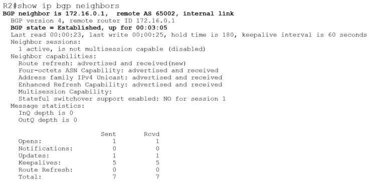
Note in the output of the ‘show IP BGP neighbors’ command above that the state of the neighbor 172.16.0.1 is ‘Established’. That is good and means the neighbor relationship is up. If you see BGP state ‘Active’, it sounds good but it's not. ‘Active’ means the router is actively trying to establish peering - and is failing. So ‘Active’ is bad, ‘Established’ is good.
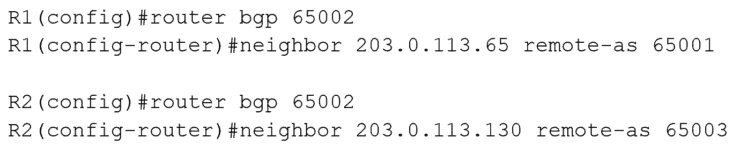
eBGP Neighbor Configuration
Okay, so we've got our iBGP neighbors configured. The next thing to do is configure our eBGP neighbors.
We use the same configuration again. The only difference is the ‘remote-as’ on the neighbor statements is different than our own AS of 65002. This tells the router we’re configuring eBGP neighbors and to apply the eBGP rules.
Once that’s done we have all the BGP neighbors configured and working. There’s not much point in doing this on its own because they’re not sharing any routing information with each other yet. We’ll cover that in the next post in this series.
Additional Resources
Part 1: Why We Need BGP
Part 2: BGP Routing and Path Selection for Service Providers
Basic BGP Configuration from Cisco Press