In this Cisco CCNA training tutorial, you’ll learn how to verify the spanning tree protocol. Scroll down for the video and also text tutorial.
Spanning Tree Verification and Troubleshooting Commands Video Tutorial

Carl Tan-awon

Yes! I passed my CCNA exam!
Last month after I got my CCNA, my applications are getting noticed by the hiring officers and I am now working as a NOC engineer in a provider.
It took 1 month of your course, a month of practice exams and a month of looking for a job.
Really thankful for your course Neil, it did really help ease my journey in this industry.
Spanning Tree Verification Example: Root Bridge
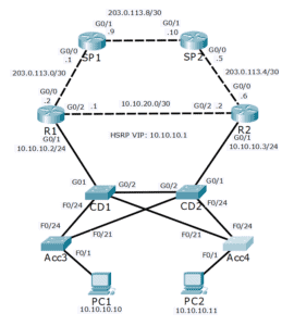
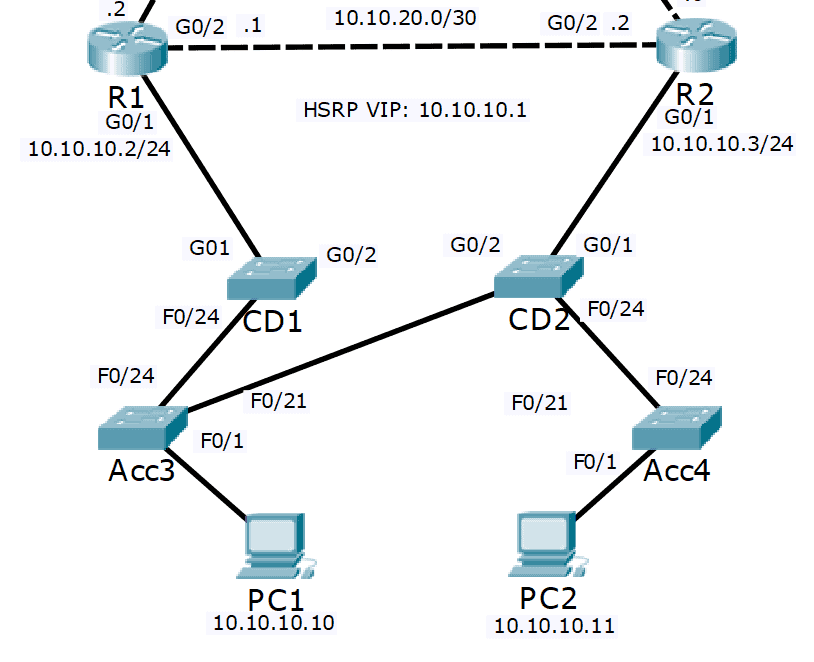
In the topology below, we've got the Layer 3 part of the network up at the top with our routers, R1 and R2, and going northbound. We've also got the Layer 2 part of the network with our core distribution switches, CD1 and CD2, and our access layer switches Acc3 and Acc4.
There's obviously Layer 3 connections going from the PCs up to the routers as their default gateways as well. What we want to do here is to map out how the spanning tree has been configured. In this example, the switches have been configured with VLANs but the spanning tree has not been configured at all, so they're all going to be using the default priority.
What we want to do here is to determine which is the root bridge first. Then from there, we can figure out our root ports on the other switches, our designated ports, and our blocking ports. Therefore, we can then check that spanning tree has eliminated any loops in the Layer 2 part of the network and we can also see the tree that traffic is going to be traveling over.
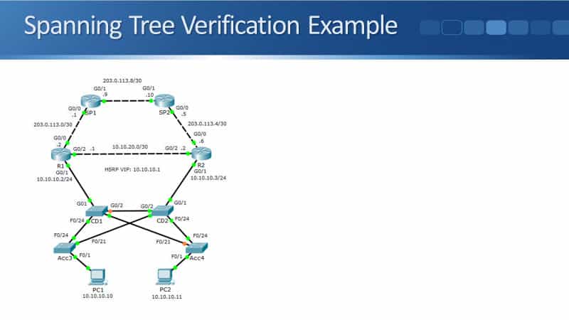
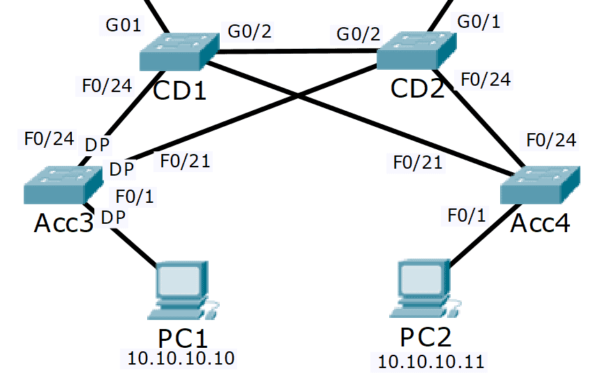
The diagram above is a screenshot from Packet Tracer. I've got the link lights enabled so you can actually see easily where the root bridge is, and the path that traffic is going to go over. Just from looking at it here, you see that both Acc3 and CD2, their links are all green. So, one of those two is going to be the root bridge.
On CD1, it's blocking a port going towards CD2. CD2 can't be the root bridge, it's going to be Acc3. I can see on Acc3 all the links going to it are green on both sides.
I can also see from the diagram that the ports that are being blocked are Gig0/2 on CD1, and port FastEthernet0/21 on Acc4. Both of the possible loops, going from CD1, CD2, Acc3, that has been broken by blocking Gig0/2 on CD1. A potential loop between CD1, CD2, and Acc4 has been broken by blocking the port FastEthernet0/21 on Acc4.
Obviously, in the real world, you're not going to have a diagram that shows you exactly how the spanning tree is configured. How do we figure out how the spanning tree is laid out in a production network? That's what we're going to cover here, using the same example topology.
Verification – show spanning-tree
The Swiss army knife command for checking your spanning tree configuration is the command:
show spanning-tree
The default spanning tree version on a Cisco switch is PVST+ which runs a separate spanning tree instance for every VLAN. Therefore, you need to specify the VLAN as well. In the example here, we're running the command first off on the root bridge, which was on Acc3 for our example.
Actually, we use the command:
show spanning-tree vlan 1
If you don't specify the VLAN, it will show you the spanning tree for all of your different VLANs. If you've got a lot of VLANs on a switch, it's going to have a very long output. So, you want to specify the particular VLAN instead.
The next thing you can see here is the protocol is IEEE. It's not actually using one of the standard IEEE spanning tree versions, it's using Cisco's proprietary PVST+. It's just a quirk of the history of how this was developed, that Cisco called PVST IEEE when you use the show spanning-tree command, using the default PVST+.
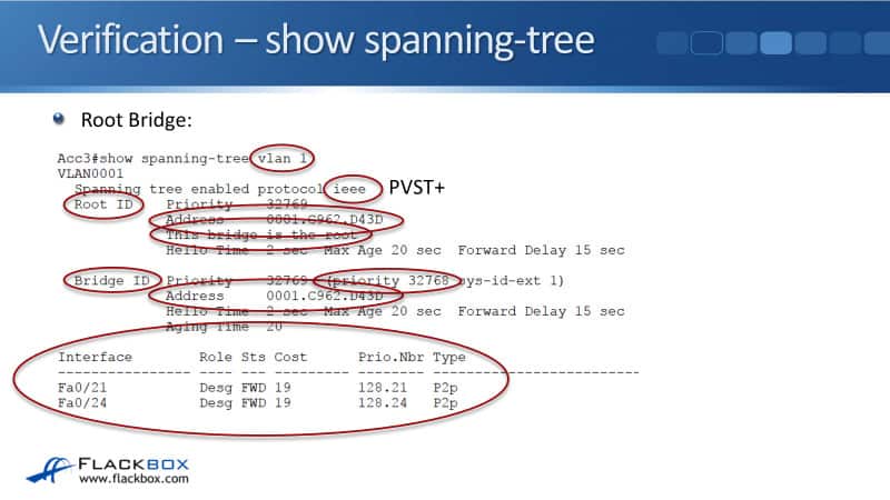
The next thing to tell you about the output of the command is that there are two sections.
- Root ID section - gives you information about the root bridge
- Bridge ID section - gives you information about this switch
The root ID information should be similar to all of the switches in your local area network. The bridge ID section will specify the MAC address for that individual switch.
Under the root ID section, it tells us this bridge is the root. That's why the MAC address is the same in the root ID section and in the bridge ID section because the switch is the root bridge. For this example, the switch's mark address ends in D43D.
We can also see the priority here, the priority is 32768, which is the default priority. This has been elected as the root bridge, so I can see very simply from this information that all my bridges, all my switches, must be set with the default priority, which is 32768. This switch was elected as the root bridge because it's got the lowest MAC address.
The last thing to see on the output of the command was it gives you the status of all your interfaces that are connected to other switches. Because this is the root bridge, all our ports are going to be designated ports and forwarding.
Spanning Tree Verification Example: Non-Root Bridge
Next, let's look at the output on a non-root bridge. We'll look at the output on CD1. From the diagram, we can see that it is forwarding on interfaces FastEthernet 0/24 and FastEthernet 0/21, and it's blocking on interface Gig0/2.

Looking at the output on CD1, I can see that this switch is also running PVST+. You want all the switches in your network to be running the same spanning tree version. Again, you've got the root ID and the bridge ID section. Because this is not the root bridge, the two MAC addresses are different now.
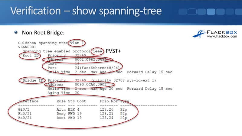
The root ID section gives you information about the root bridge. You want all of the switches in your network for the same VLAN to be agreeing on which switch this is. We can see that it is the same, D43D.
In the bridge ID section, I can see that this switch's unique mark address ends in 3902. This switch's mark address starts with 0090, which is higher than the root bridge's mark address of 0001, that's why the root bridge was preferred over this one.
Other information in the root ID section is that I can see that this switch's cost to get to the root bridge is 19, and the root port is interface FastEthernet0/24. That's the least cost path interface to get to the root bridge.
Down at the bottom, I can see that interface Gig0/2, its role is alternate, so it is a blocking port. It's a port that has been selected to block a potential loop. Interfaces FastEthernet0/21 and 0/24 are designated in a root port, and they are both forwarding.
If we look at the topology diagram again, on CD2, all its interfaces should be forwarding. In the lab, I will issue the commands enable prompt and show spanning tree for VLAN 1.
In here, I can see that it agrees that the root bridge is Acc3, ending with MAC address D43D. This switch's MAC address also begins with 0090, so it's a higher MAC. That's why it was not selected as the root bridge. All of my switches are running the default priority of 32768.
For this switch to get out to the root bridge, it uses interface FastEthernet0/21, and the cost is 19. I can see all of my ports are connected to other switches down at the bottom here. FastEthernet0/21 is the root port. The other two ports are designated ports, so all of these ports are forwarding.
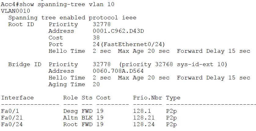
Finally, the last switch to look at is Acc4, which is forwarding on FastEthernet0/24. That is the root port, and it's blocking on FastEthernet0/21. Let's jump onto Acc4 in the lab. I can see that it also agrees that the root bridge is Acc3. This switch's MAC address begins with 0060, which is higher than the root bridge's MAC address.
All of my switches are using a priority 32768. The root port is FastEthernet0/24, and the cost to get to the root bridge is 38. We're forwarding on port FastEthernet0/24, and we're blocking on port FastEthernet0/21.
That's how you can check your spanning tree topology. There's not really a quick way of doing this. If you just have command line access to your switches, jump on one of your switches and do show spanning tree there. That will tell you which is the root bridge.
To find the entire topology, and to see which ports are forwarding and which are blocking, you really just have to map it out switch by switch. So it's handy if you use a pencil and paper for this. You can draw it down and diagram everything.
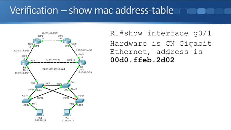
Verification – show mac address-table
Another command you can use to check the path that traffic is taking throughout your layer two network is:
show mac address-table
For this example, we're going to check the path that traffic is taking from PC1 going to R1. You can see in the diagram that it should go from PC1 to Acc3 to CD1 to R1.
I go into R1 and I do a show interface for Gig0/1 there, to find out the MAC address, because I'm going to check the path traffic's taking from PC1 to that interface, with IP address 10.10.10.02. Any example I can see that it ends with MAC address 2D02.
I then go onto the first hot switch which is Acc3 and enter the command show mac address-table. I see the entry there for VLAN 1. The MAC address ending in 2D02, which is that interface in R1 that the outgoing port is going to be FastEthernet0/24, going towards CD1.

Then I go into the next top of CD1, and I do a show mac address-table there, and I can see that the MAC address was learned in interface Gig0/1, so again, that was what I expected, going directly to R1.

For the traffic going from PC2 to R1, we expect the traffic to go from PC2 to Acc4 to CD2 to Acc3 to CD1 and then to R1. First off, let's go on to R1 and check the MAC address. I'll go to the command line and input show interface Gig0/1. That's the interface with IP address 10.10.10.02. I can see that the MAC address ends in 2D02.
Then, I will go on to PC2, and open up a command prompt. I'll clear my art cache first, and then I'll ping 10.10.10.02 to generate some traffic so that the switches in the path will learn the MAC address. Then, looking at the topology diagram, PC2s first hop is Acc4, and I expect that the traffic will go out interface 0/24.
Let's now go onto the Acc4 switch, and do a show mac address-table command on here, look for the entry for 2D02 and that the traffic is going out FastEthernet0/24. That will go to CD2, and I expect the traffic out CD2 to go out interface FastEthernet0/21. I issue the command show mac address-table on here, look for the entry to 2D02 going out interface FastEthernet0/21.
The next hop is going to hit Acc3 because it comes out FastEthernet0/21 and CD2. on Acc3, I expect it to be forwarded out, FastEthernet0/24 to CD1. So on Acc3, we enter show mac address-table, and 2D02, yes, is on FastEthernet0/24.
Finally, the last hop is going to be CD1. It should be on interface Gig0/1. Let's go on to CD1, and issue a show mac address-table on here. There it is, 2D02 and it is going out interface Gig0/1.
That's how you can verify the spanning tree, by mapping out your root ports, your designated ports, and your alternate blocking ports. Also, how you can use a show mac address-table command to verify that traffic will be going through that path.
Spanning Tree Verification and Troubleshooting Commands Configuration Example
This configuration example is taken from my free ‘Cisco CCNA Lab Guide’ which includes over 350 pages of lab exercises and full instructions to set up the lab for free on your laptop.
Click here to download your free Cisco CCNA Lab Guide.
- The Network Operations Centre has reported that traffic is not following the most direct path from the branch office PCs to the Internet. Your task at this stage is to verify this.
There is not a set order of actions to troubleshoot this scenario. Troubleshooting in a logical fashion will however make it easier and quicker. This is how I would do it.
Check which router is the HSRP active gateway for the 10.10.10.0/24 network.
R1#show standby
GigabitEthernet0/1 - Group 1
State is Active
7 state changes, last state change 00:28:52
Virtual IP address is 10.10.10.1
Active virtual MAC address is 0000.0C07.AC01
Local virtual MAC address is 0000.0C07.AC01 (v1 default)
Hello time 3 sec, hold time 10 sec
Next hello sent in 2.276 secs
Preemption enabled
Active router is local
Standby router is 10.10.10.3, priority 100 (expires in 7 sec)
Priority 110 (configured 110)
Group name is hsrp-Gig0/1-1 (default)
R1 has been preconfigured with a higher HSRP priority and pre-emption enabled.
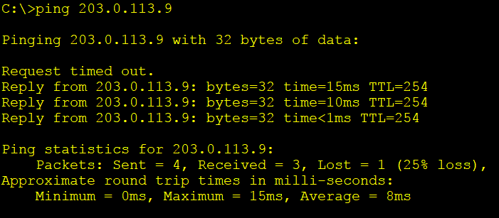
2. Check the PCs have connectivity to 203.0.113.9. Ping from both PCs.
3. Check which Layer 3 path the PCs are using to get to 203.0.113.9. Run traceroute on both PCs.
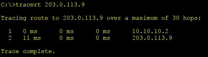
The PCs are taking the most direct path via their HSRP default gateway to get to 203.0.113.9. The Layer 3 configuration and operations all look good.
4. Check which VLAN the PCs are in on the Acc3 and Acc4 switches.
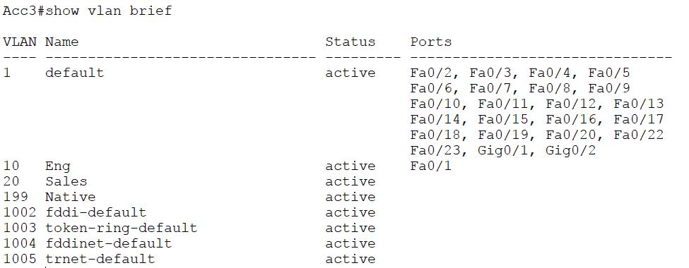
The PCs are in the Eng VLAN 10.
5. On CD1 and CD2, check the switch ports connecting to the routers have also been configured as access ports in VLAN 10.
CD1#sh run
! truncated
interface GigabitEthernet0/1
switchport access vlan 10
switchport mode access
On all switches, check the interfaces connecting switches have been configured as trunks with matching native VLANs.
CD1#sh run
! truncated
!
interface FastEthernet0/21
switchport trunk native vlan 199
switchport mode trunk
!
interface FastEthernet0/24
switchport trunk native vlan 199
switchport mode trunk
!
interface GigabitEthernet0/2
switchport trunk native vlan 199
switchport mode trunk
The existing HSRP and VLAN configuration looks good.
6. The next thing to verify is Spanning Tree. One of the central core/distribution switches should be used as the Root Bridge to ensure Layer 2 traffic uses the most direct path over the network.
Check the Spanning Tree topology for VLAN 10 on switch Acc3.
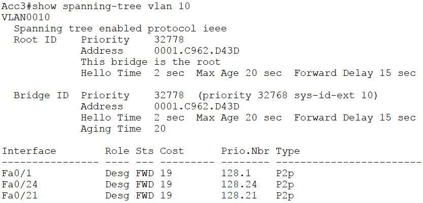
7. Acc3 is the Root Bridge. That is not good. Check to see if this is because it has a configured Bridge Priority.
Acc3#sh run | include priority
Acc3#
Bridge Priority has not been configured on Acc3. Check the other switches.
CD1#sh run | include priority
CD1#
CD2#sh run | include priority
CD2#
Acc4#sh run | include priority
Acc4#
Bridge Priority has not been configured anywhere so the switch with the lowest MAC address should be selected as the Root Bridge.
We learned that Acc3’s MAC address is 0001.C962.D43D from the output of the ‘show spanning tree vlan 10’ command we ran on it.
8. Verify that all switches have matching Spanning Tree Root Bridge information. They should all have the same default Bridge Priority value (as one was not manually set), and agree that Acc3 has the lowest MAC address and is the Root Bridge.
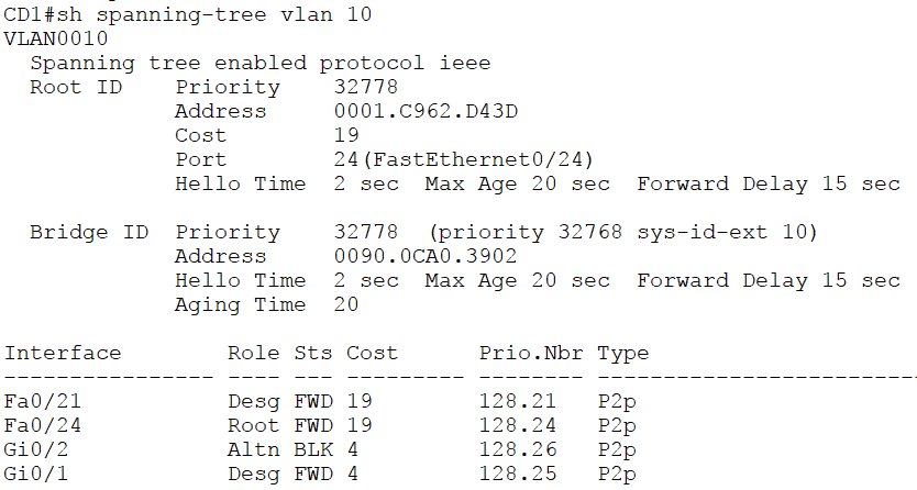
CD1’s MAC address is 0090.0CA0.3902. It agrees that Acc3 is the Root Bridge.
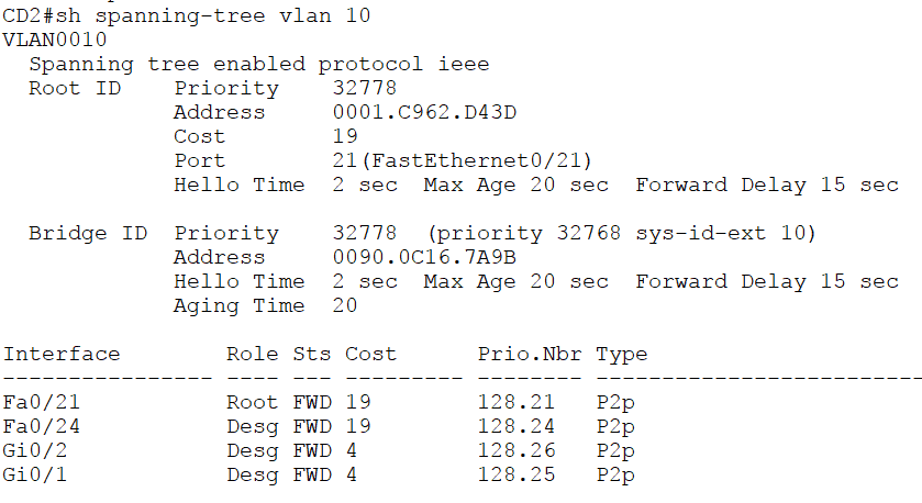
CD2’s MAC address is 0090.0C16.7A9B. It agrees that Acc3 is the Root Bridge.
Acc4’s MAC address is 0060.708A.D564. It agrees that Acc3 is the Root Bridge.
9. We were asked to report on the forwarding paths currently being used. Use the output of the ‘show spanning-tree vlan 10’ commands on each switch to diagram the Spanning Tree.
Acc3 is the Root Bridge so all its ports are Designated Ports.
10. Add each switch’s Root Port to the diagram. The ‘Port’ value in the ‘Root ID’ section of the ‘show spanning-tree vlan 10’ output shows this information.
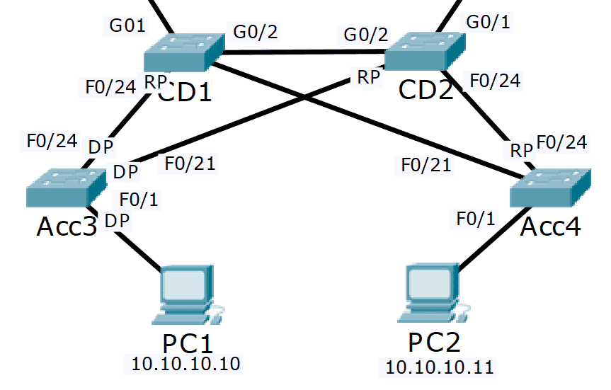
The port on the other side of Root Ports is always a Designated Port. Label F0/24 on CD2 as a Designated Port in the diagram.
11. The links which are left must be blocking. These are CD1 G0/2 to CD2 G0/2, and CD1 F0/21 to Acc4 F0/21. Check which side is blocking from the output of the ‘show spanning-tree vlan 10’ commands.
CD1 G0/2 is the blocking Alternate port, CD2 G0/2 is the forwarding Designated Port.
CD1 F0/21 is the forwarding Designated Port, Acc4 F0/21 is the blocking Alternate port.
Add this information to the diagram.
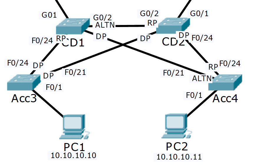
12. By removing the blocking links from the diagram we can see the Spanning Tree.
We can see that PC1 will take the path PC1 > Acc3 > CD1 > R1 to reach its HSRP default gateway. This is the most direct path and is good.
The end to end path from PC1 to 203.0.113.9 is PC1 > Acc3 > CD1 > R1 > SP1
PC2 however will use the path PC2 > Acc4 > CD2 > Acc3 > CD1 > R1. This is not the most direct path as traffic is transiting CD2 and Acc3 rather than going directly over the link from Acc4 to CD1.
The end to end path from PC2 to 203.0.113.9 is PC2 > Acc4 > CD2 > Acc3 > CD1 > R1 > SP1
13. We can verify the path being used by checking the MAC address tables on the switches. First, verify the HSRP virtual MAC address.
R1#sh standby
GigabitEthernet0/1 - Group 1
State is Active
5 state changes, last state change 00:00:30
Virtual IP address is 10.10.10.1
Active virtual MAC address is 0000.0C07.AC01
14. Then clear the ARP cache on PC2, and ping the virtual IP address to generate traffic.
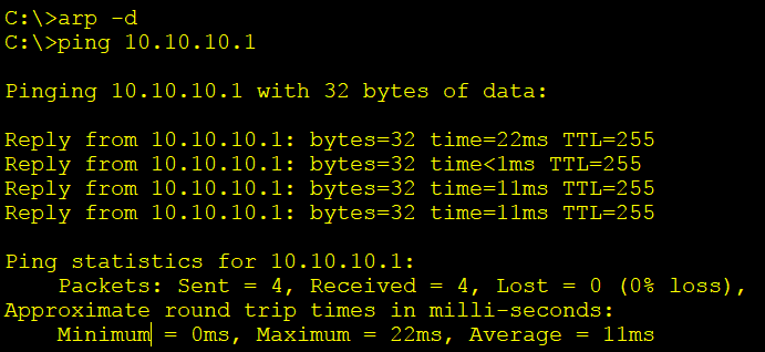
15. Then check the MAC address table on Acc4.
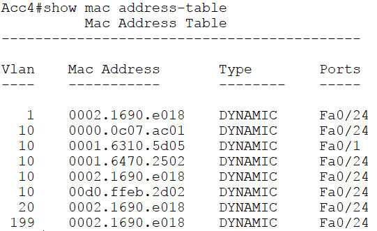
We can see that the HSRP virtual MAC address 0000.0c07.ac01 is reached through interface F0/24 to CD2, rather than on the direct link to CD1 over interface F0/21.
We can go hop by hop using the ‘show mac address-table’ command to verify the traffic path end to end across the switched network.
Additional Resources
STP: https://www.ciscopress.com/articles/article.asp?p=2832407&seqNum=6
How to configure and verify Spanning Tree Protocol (STP) PortFast: https://www.omnisecu.com/cisco-certified-network-associate-ccna/how-to-configure-and-verify-spanning-tree-protocol-stp-portfast.php
Spanning Tree Protocol (STP) Overview: https://documentation.meraki.com/MS/Port_and_VLAN_Configuration/Spanning_Tree_Protocol_(STP)_Overview
Libby Teofilo

Text by Libby Teofilo, Technical Writer at www.flackbox.com
Libby’s passion for technology drives her to constantly learn and share her insights. When she’s not immersed in the tech world, she’s either lost in a good book with a cup of coffee or out exploring on her next adventure. Always curious, always inspired.