In this Cisco CCNA tutorial, you’ll learn about a basic initial configuration to put on your routers and switches. Scroll down for the video and also text tutorial.
Cisco Basic Router and Switch Configuration Video Tutorial
Matt Baker

Hi Neil, I just passed the new CCNA 30 minutes ago. Thank you so much for your content, updating it, answering people’s questions, and genuinely caring. It is much appreciated, it makes a difference.
Router IP Addresses
One of the first things it will do is configure IP addresses. Your routers provide connectivity between your different IP subnets, and that’s their main job. The routers need to have interfaces in the different subnets, and they need to have IP addresses on those interfaces.
Those IP addresses will act as the default gateway address for any hosts that are in that subnet. The command to put an IP address on an interface goes to the interface.
For example, we’ve got a router down at the bottom. The interface FastEthernet0/0 on the right has an IP address 192.168.0.1/24, and the interface on the left, FastEthernet0/1, has an IP address 192.168.1.1 /24. The IP addresses need to be in different subnets that are on different interfaces.
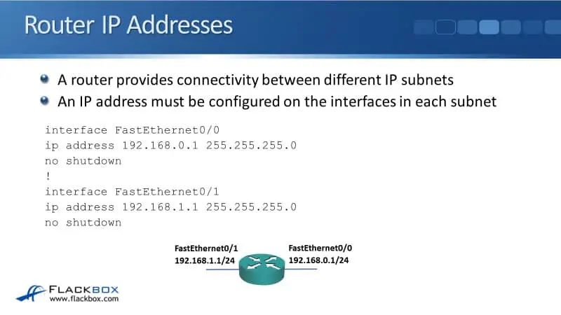
From the global configuration mode, we go to interface configuration mode using the command ‘interface FastEthernet0/0’. Then to put the IP address on there, add ‘ip address’, space, ‘192.168.0.1’, then another space, and then the ‘subnet mask 255.255.255.0’.
The IP address and the subnet mask are both entered with one command, and you must enter the subnet mask in full dotted decimal notation. You can’t enter /24 in IOS.
On our routers, interfaces are shut down by default. Use the ‘no shutdown’ command to bring the interface up. So we do that for interface FastEthernet0/0, and then we also need to configure interface FastEthenet0/1. It gets IP address 192.168.1.1, subnet mask 255.255.255.0, 'no shutdown'.
After configuring this, the router can route traffic between those two networks. As well as being able to route traffic, it also gives IP connectivity to the router itself. So after we’ve done this, we could open up a Telnet or SSH client, like Putty, and connect to the router to manage it.
So obviously, this is more convenient than having a walk down there with a console cable and hook it up physically every time. Once you’ve got IP addresses on your router, you’ll be able to connect to those IP addresses to manage the router remotely from wherever you are.
Switch Management IP Address
We’re also going to need an IP address on our switch to manage that as well. A Layer 2 switch is not IP routing aware and does, however, support a single IP address used for management. You can’t put multiple IP addresses on a Layer 2 switch, and it will only allow you to put one IP address. To manage it, we can again Telnet or Secure Shell (SSH) to the switch remotely.
Unlike on a router, where we configure the IP address on an interface, on a switch, a Layer 2 switch, the management IP address goes on a VLAN interface, a virtual interface. So when we configure our VLAN interface, that’s called an SVI, Switched Virtual Interface, which will be in VLAN 1.
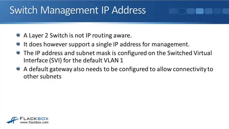
Now, I know we haven’t covered VLANs yet. They’re going to be configured in another section, for all you need to know for now is that the default VLAN is VLAN 1, and all of our Layer 2 switch ports on a switch will be in VLAN 1 by default.
We configure our management IP address on the virtual VLAN 1 interface to get management connectivity to the switch. That will allow us to connect to the switch from the same IP subnet that the IP address is in.
However, our administrators will probably be located somewhere else, and they will be in a different IP subnet, so this switch also needs to be able to get out to that subnet. Like a normal host would need, it will also need a default gateway.
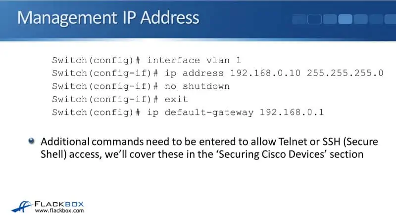
Our configuration on our switch for our management IP address, ‘interface vlan 1’, then we configure the IP address the same way. So I’ve got IP address 192.168.0.10, subnet mask 255.255.255.0. Now, interfaces are shut down on a router by default, and on a switch, interfaces are enabled by default. So there wasn’t any need to do a ‘no shutdown’ here.
However, I’m just in the practice that whenever I configure an interface, I always do a ‘no shutdown’ on there. It doesn’t do any harm, and it saves me having to think, “Do I need to do a ‘no shutdown’ or not?” Just always do a ‘no shutdown’ whenever you configure an interface, which saves you from forgetting it.
We exit to global configuration mode, and to configure the default gateway, the command is ‘ip default-gateway 192.168.0.1’. That will give us IP connectivity on this switch, and we’ll be able to ping this switch and ping it out. Now, I said that this IP address is for management. We still need to do some additional commands to allow Telnet and/or SSH access to the switch.
Lab Example
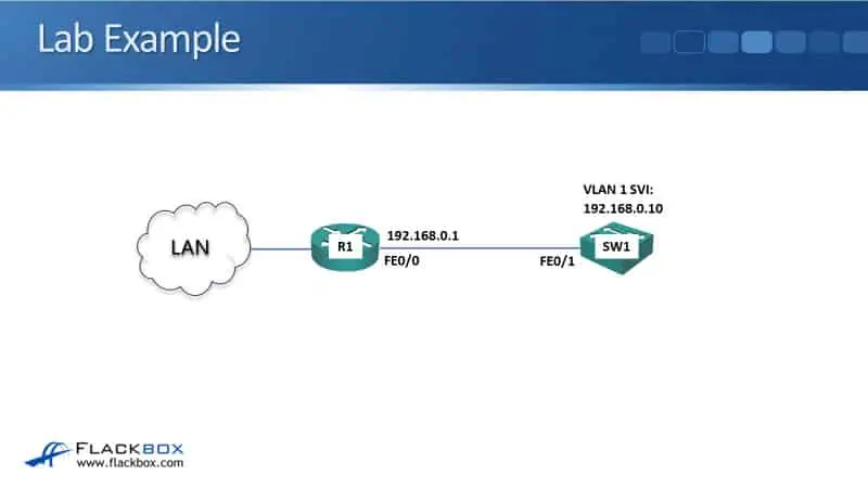
Let’s look at how to do this in the lab. For the lab example, we’ve got router R1, and we’ll configure IP address 192.168.0.1 on the physical interface FastEthernet0/0. That’s going to be the default gateway address for our switch, which is SW1. SW1 will be connected to the router through the physical interface FastEthernet0/1, which will be in VLAN 1 by default.
For the management IP address, we will configure that on the VLAN 1 Switched Virtual Interface. We’ll give that IP address 192.168.0.10. Once we’ve done that, the switch should have connectivity to 192.168.0.1 because it’s on the same subnet.
However, we want it to have connectivity to other subnets out through the router. So we’ll also configure the switch with an IP default gateway address of 192.168.0.1.
I better configure the router first because it also has a new configuration. So I’ll go ’enable’, ’configure terminal’, ’interface FastEthernet0/0’. I will give that IP address 192.168.0.1, ’ip address 192.168.0.1 255.255.255.0’. I have to remember to do a ‘no shutdown’ on here. Okay, so that’s the router configured.
Then I go to the switch and enter ‘enable’ and ‘configure terminal’. This was on the VLAN interface, so ‘interface vlan 1’ and ‘ip address 192.168.0.10 255.255.255.0’. It is not shut down by default anyway, but it doesn’t do any harm by doing a ‘no shutdown’ on the interface. Now the switch should be able to communicate with the router. Let’s check that.
I’ll go back down to the enable prompt and go ‘ping 192.168.0.1’, and we’ve got connectivity. That’s all good, and I’ve got connectivity on my 192.168.0.0 subnet. But I want to be able to get out to other subnets as well, so I need to configure the default gateway. The command for that is ‘ip default-gateway 192.168.0.1’. That is the initial IP connectivity configured there.
Hostname
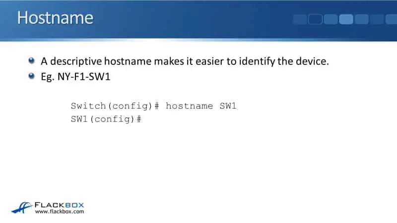
The next thing we want to do for the basic configuration is to configure a hostname. A descriptive hostname makes it easier to identify the device. For example, I could maybe call it New York-F1-Switch1. So typically, you will specify where the Switch is and perhaps some other descriptive description there. In the lab, I’m just going to call it ‘hostname SW1’ for Switch 1.
The default hostname on a switch is just Switch. That’s what is showing up on the command prompt. When I enter ‘hostname SW1’ and hit enter, the command prompt immediately changes to show the hostname.
This is useful because a common mistake is configuring the wrong device by accident. Having the hostname showing up here makes it a little bit less likely that you’re going to do that. So it gives you a nice description, and you can see what device you’re on.
Also, if you’re troubleshooting from neighboring devices, it will show up as its hostname as well, so it just makes it easy to see what’s going on.
Interface Descriptions
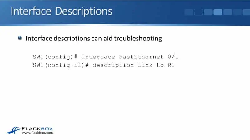
Next, we’ll want to configure our interfaces’ descriptions. Interface FastEthernet 0/1 was connected to the router, so let’s put a description there. Back to the command line, I go to interface FastEthernet 0/1, and I’ll say ‘description Link to R1’.
Again, this is going to be useful for troubleshooting later. If I’m troubleshooting and looking at the configuration here, I can immediately see that FastEthernet 0/1 is the interface connected to router R1.
Additional Resources
Basic Router Configuration: https://www.cisco.com/c/en/us/td/docs/routers/access/800M/software/800MSCG/routconf.html
Cisco Networking Academy's Introduction to Basic Switching Concepts and Configuration: https://www.ciscopress.com/articles/article.asp?p=2181836&seqNum=4
Cisco IOS Router Basic Configuration: https://networklessons.com/cisco/ccna-routing-switching-icnd1-100-105/cisco-ios-router-basic-configuration
Configure an IP Address on a Switch: https://study-ccna.com/configure-an-ip-address-on-a-switch/
Libby Teofilo

Text by Libby Teofilo, Technical Writer at www.flackbox.com
Libby’s passion for technology drives her to constantly learn and share her insights. When she’s not immersed in the tech world, she’s either lost in a good book with a cup of coffee or out exploring on her next adventure. Always curious, always inspired.