In this Cisco CCNA training tutorial, you’ll learn how BGP is used for layer 3 MPLS VPNs. Scroll down for the video and text tutorial.
Cisco BGP in MPLS Networks Video Tutorial

Brando Welgemoed

I would just like to thank you for helping me with my CCNA, I passed it a few months ago. You really helped me out of a hard situation in life where I had no job. I am currently working as a network engineer and my life is coming back together.
Layer 3 MPLS VPN
In the diagram shown below, you can see that:
- The provider network is going from the PE on the left to the PE on the right.
- Core P routers are there in the middle.
- Customer Edge (CE) routers are going to connect to the PEs.
- The providers provide a layer 3 MPLS VPN, thus, our different customer sites will be able to communicate with each other.

For Customer A at the top, all of their sites can talk to each other. Similarly, for Customer B at the bottom, all of their sites can talk to each other as well.
MPLS runs across the provider’s core on the PE and P routers. The customer CE routers do not run MPLS. Looking at the diagram again, we've got MPLS configured on the two PEs, and the P router is configured on the provider devices.
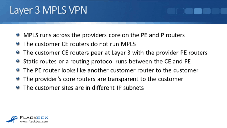
The CE routers do not have MPLS enabled. They're not MPLS aware at all. The customer CE routers peer at Layer 3 with the provider PE routers.
They see the provider router, and they're going to exchange routes with the provider router as well using any of these two methods:
- Static Routes
- Routing Protocols
The PE router looks just like another customer router to the customer. The provider's core routers are transparent to the customer, it can't see them.
The customer sites are in different IP subnets. If you look at Customer A, they've got 10.0.0.0/24 at the top left and 10.0.1.0/24 at the top right.
CE Router Configuration - Static Routes
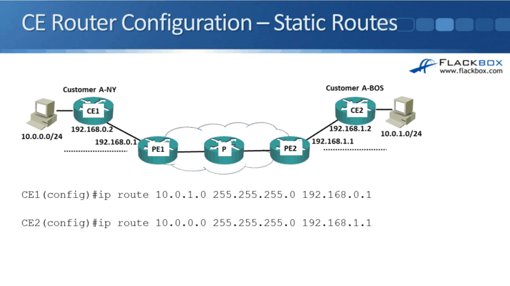
We will configure the static routes and the CEs as shown below.
Here is what we did during the configuration:
- On CE1, we configured a route, IP route 10.0.1.0, pointing to the site in the top right. The subnet mask is /24 and the next hop address is PE1 at 192.168.0.1
- On CE2, we've got IP route 10.0.0.0 pointing to the site on the left. The subnet mask is /24 and the next hop address is 192.168.1.1 on PE2.
Now, we've got our static routes and the CEs pointing to the PEs.
PE Router Configuration
We will also need to have static routes on the PEs pointing to the CEs as well. So now, we're getting into the service provider part of the configuration.

This is how the service provider configuration is done:
- On PE1, we've got an IP route for 10.0.0.0/24, pointing at 192.168.0.2, router CE1.
- On PE2, we've got an IP route 10.0.1.0, 255.255.255.0, pointing at CE2 at 192.168.1.2.
At that point, CE1 knows it has to send traffic to PE1 when it's trying to get over at CE2, and CE2 knows to send traffic to PE2 when it wants to send traffic over to CE1.
PE1 knows how to get to CE1, and PE2 knows how to get to CE2, but we don't have end-to-end connectivity yet. PE2 does not know that it needs to go via PE1 to get to CE1 and PE1 does not know that it needs to go via PE2 to get to CE2.
End-to-End Connectivity
To have end-to-end connectivity, PE 1 and PE 2 need to share the static routes with each other. We need a way to share those routes with one another.
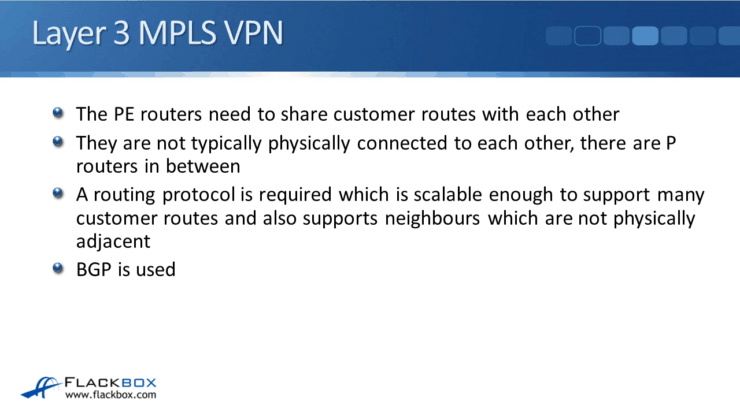
The PE routers are not typically physically connected to each other. There are usually going to be P core routers in between them. Therefore, our routing protocol is required to:
- Share these routes between PE routers and P routers,
- Ensure routes are scalable enough to support many customer routes,
- Support neighbors, which are not physically adjacent.
That sounds a lot like BGP, right? Yes, that's what we are going to use. BGP is used internally between the two PE routers to share the customer routes with each other.
PE Router Configuration – BGP
As shown in the diagram below, PE 1 tells PE 2 that "Customer A can get to 10.10.0.0/24 via me," and then routes to the customer site on the left.
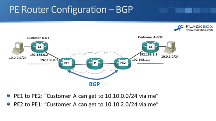
Similarly, PE 2 tells PE 1 that "Customer A can get to 10.10.2.0/24 via me," and then routes to the site on the right. We use BGP to share the customer routes between the two PE routers. That gives us full end-to-end connectivity.
The P routers at the provider don't know anything about the customer routes. It is directly between the PE routers which makes it a more scalable solution.
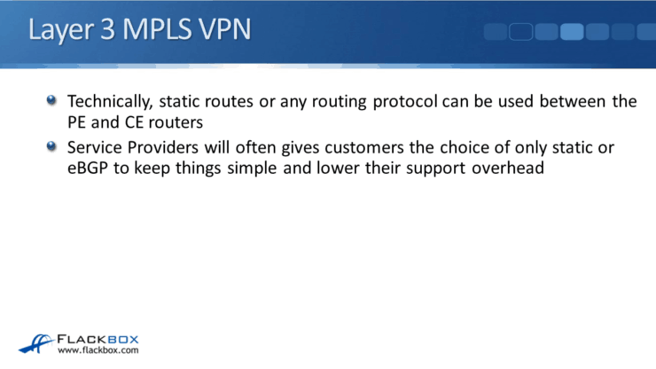
Technically, static routes or any routing protocol like RIP, EIGRP, SPF, etc., can be used between the PE and the CE routers.
Service providers will often give customers the choice of only static eBGP to keep things simple and lower their support overhead.
They don't want to have to support all of those different routing protocols, so they just say static or eBGP, which are simple. The providers do this because they know BGP very well, and they're already using BGP between the two PE routers.
CE Router Configuration – eBGP
For the eBGP, we would be looking at CE 1 configuration first.

The router BGP 65010 is used for the provider AS. For this, we're using all private IP addresses here.
We're not doing internet routing, so the customer doesn't actually need to buy an AS from the internet authorities. They can use a private AS number.
The ASes that begin with 65 are private, that's why I've been using them in the example. They can use the command:
neighbor 192.168.0.1 remote-as 65001
They're also using AS 65010, which is a private BGP. AS doesn't need to be registered and they also need to advertise their internal network in BGP so, they issue the command:
network 10.0.0.0 mask 255.255.255.0
At this point, CE1 will form a BGP relationship with PE1 and the provider will configure the PE1 side. CE1, using eBGP, will advertise its internal networks over to PE1 then, PE1 will carry them in iBGP over to PE2.
We would also need to have eBGP set up between PE2 and CE2.
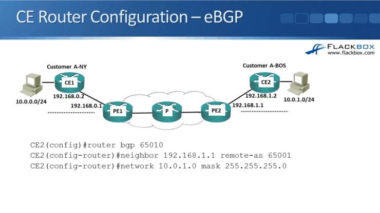
Our configuration on CE2 is the same configuration that we had on CE1:
router bgp 65010
neighbor 192.168.1.1 remote-as 65001
network 10.0.1.0, mask 255.255.255.0
It would create an eBGP relationship with PE2 and it would advertise the network to PE2 using BGP.
That's how MPLS Layer 3 VPNs work. Usually, it's either static routes or eBGP running from the CE to the PE routers.
Tips for CCNA Exam
When you take the CCNA exam, you don't need to know how things are working internally in the service provider, or how to configure it. But, I've been showing you that so you can see how it works end-to-end and really understand the whole solution.
For the CCNA exam, you would need to:
- Know configuration from the customer point of view.
- Know, understand, and be able to configure BGP for a customer for internet routing if they're connected to two different service providers.
- Know how to configure BGP for MPLS Layer 3 VPNs as well, as shown in here.
Since it's eBGP, our verification commands will be the same as usual:
- 'show ip bgp summary' to check that the neighbor has come up.
- 'show ip bgp' to check that routes are being received via BGP.
- 'show ip route' to check that they're making it into the routing table.
BGP in MPLS Networks Configuration Example
This configuration example is taken from my free ‘Cisco CCNA Lab Guide’ which includes over 350 pages of lab exercises and full instructions to set up the lab for free on your laptop.
Click here to download your free Cisco CCNA Lab Guide.
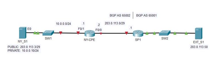
1. Configure IP addresses on the NY-CPE router’s FastEthernet0/0 and FastEthernet0/1 interfaces according to the lab topology diagram.
NY-CPE(config)#int f0/0
NY-CPE(config-if)#ip add 203.0.113.2 255.255.255.248
NY-CPE(config-if)#no shut
NY-CPE(config-if)#int f0/1
NY-CPE(config-if)#ip add 10.0.0.1 255.255.255.0
NY-CPE(config-if)#no shut
2. Verify the interfaces come up.
NY-CPE#sh ip int brief
Interface IP-Address OK? Method Status Protocol
FastEthernet0/0 203.0.113.2 YES manual up up
FastEthernet0/1 10.0.0.1 YES manual up up
FastEthernet1/0 unassigned YES unset administratively down down
FastEthernet1/1 unassigned YES unset administratively down down
Vlan1 unassigned YES unset administratively down down
3. Check the NY_S1 server can ping its NY-CPE default gateway.
C:\>ping 10.0.0.1
Pinging 10.0.0.1 with 32 bytes of data:
Reply from 10.0.0.1: bytes=32 time<1ms TTL=255
Reply from 10.0.0.1: bytes=32 time<1ms TTL=255
Reply from 10.0.0.1: bytes=32 time<1ms TTL=255
Reply from 10.0.0.1: bytes=32 time<1ms TTL=255
Ping statistics for 10.0.0.1:
Packets: Sent = 4, Received = 4, Lost = 0 (0% loss),
Approximate round trip times in milli-seconds:
Minimum = 0ms, Maximum = 0ms, Average = 0ms
4. Check NY-CPE can ping SP1.
NY-CPE#ping 203.0.113.1
Type escape sequence to abort.
Sending 5, 100-byte ICMP Echos to 203.0.113.1, timeout is 2 seconds:
!!!!!
Success rate is 100 percent (5/5), round-trip min/avg/max = 0/0/0 ms
5. Do you expect NY-CPE to have connectivity to EXT_S1? Why or why not?
NY-CPE does not have connectivity outside its directly connected networks.
NY-CPE#ping 203.0.113.50
Type escape sequence to abort.
Sending 5, 100-byte ICMP Echos to 203.0.113.50, timeout is 2 seconds:
.....
Success rate is 0 percent (0/5)
NY-CPE#sh ip route
Codes: L - local, C - connected, S - static, R - RIP, M - mobile, B - BGP
D - EIGRP, EX - EIGRP external, O - OSPF, IA - OSPF inter area
N1 - OSPF NSSA external type 1, N2 - OSPF NSSA external type 2
E1 - OSPF external type 1, E2 - OSPF external type 2
i - IS-IS, su - IS-IS summary, L1 - IS-IS level-1, L2 - IS-IS level-2
ia - IS-IS inter area, * - candidate default, U - per-user static route
o - ODR, P - periodic downloaded static route, H - NHRP, l - LISP
+ - replicated route, % - next hop override
Gateway of last resort is not set
10.0.0.0/8 is variably subnetted, 2 subnets, 2 masks
C 10.0.0.0/24 is directly connected, FastEthernet0/1
L 10.0.0.1/32 is directly connected, FastEthernet0/1
203.0.113.0/24 is variably subnetted, 2 subnets, 2 masks
C 203.0.113.0/29 is directly connected, FastEthernet0/0
L 203.0.113.2/32 is directly connected, FastEthernet0/0
6. Do you expect the NY_S1 server to have connectivity to EXT_S1? Why or why not?
NY_S1 does not have connectivity to EXT_S1 as its default gateway NY-CPE does not have a route to it.
C:\>ping 203.0.113.50
Pinging 203.0.113.50 with 32 bytes of data:
Request timed out.
Request timed out.
Request timed out.
Request timed out.
Ping statistics for 203.0.113.50:
Packets: Sent = 4, Received = 0, Lost = 4 (100% loss)
7. Configure an eBGP peering relationship on NY-CPE with SP1 according to the lab topology diagram. NY-CPE should advertise the company’s public IP addresses in BGP. Ensure you use the correct /29 subnet mask when entering the ‘network’ statement. BGP will not advertise a route unless an exact match is found in the routing table.
NY-CPE(config)#router bgp 65002
NY-CPE(config-router)#neighbor 203.0.113.1 remote-as 65001
NY-CPE(config-router)#network 203.0.113.0 mask 255.255.255.248
8. Verify the BGP session is established successfully.
NY-CE#show ip bgp summary
BGP router identifier 10.0.0.1, local AS number 65001
BGP table version is 5, main routing table version 5
2 network entries using 576 bytes of memory
2 path entries using 320 bytes of memory
1/2 BGP path/bestpath attribute entries using 544 bytes of memory
2 BGP AS-PATH entries using 48 bytes of memory
0 BGP route-map cache entries using 0 bytes of memory
0 BGP filter-list cache entries using 0 bytes of memory
BGP using 1488 total bytes of memory
BGP activity 2/0 prefixes, 2/0 paths, scan interval 60 secs
Neighbor V AS MsgRcvd MsgSent TblVer InQ OutQ Up/Down State/PfxRcd
203.0.113.1 4 65001 7 6 3 0 0 00:06:30 4
9. Verify the 203.0.113.32/27 Internet route has been learned via BGP and is in the BGP table.
NY-CE#show ip bgp
BGP table version is 5, local router ID is 203.0.113.2
Status codes: s suppressed, d damped, h history, * valid, > best, i - internal,
r RIB-failure, S Stale, m multipath, b backup-path, f RT-Filter,
x best-external, a additional-path, c RIB-compressed,
Origin codes: i - IGP, e - EGP, ? - incomplete
RPKI validation codes: V valid, I invalid, N Not found
Network Next Hop Metric LocPrf Weight Path
*> 203.0.113.0/29 0.0.0.0 0 0 32768 i
*> 203.0.113.32/27 203.0.113.1 0 0 0 65001 i
10. Verify NY-CE has routes to the 203.0.113.32/27 Internet network in its routing table, with SP1 as the next hop.
NY-CE#show ip route
Codes: L - local, C - connected, S - static, R - RIP, M - mobile, B - BGP
D - EIGRP, EX - EIGRP external, O - OSPF, IA - OSPF inter area
N1 - OSPF NSSA external type 1, N2 - OSPF NSSA external type 2
E1 - OSPF external type 1, E2 - OSPF external type 2
i - IS-IS, su - IS-IS summary, L1 - IS-IS level-1, L2 - IS-IS level-2
ia - IS-IS inter area, * - candidate default, U - per-user static route
o - ODR, P - periodic downloaded static route, H - NHRP, l - LISP
+ - replicated route, % - next hop override
Gateway of last resort is not set
10.0.0.0/8 is variably subnetted, 2 subnets, 2 masks
C 10.0.0.0/24 is directly connected, FastEthernet0/1
L 10.0.0.1/32 is directly connected, FastEthernet0/1
203.0.113.0/24 is variably subnetted, 3 subnets, 3 masks
C 203.0.113.0/29 is directly connected, FastEthernet0/0
L 203.0.113.2/32 is directly connected, FastEthernet0/0
B 203.0.113.32/27 [20/0] via 203.0.113.1, 00:00:00
11. Do you expect NY-CPE to have connectivity to EXT_S1 now? Why or why not?
NY-CPE has connectivity to EXT_S1 now because Internet connectivity has been established.
NY-CPE#ping 203.0.113.50
Type escape sequence to abort.
Sending 5, 100-byte ICMP Echos to 203.0.113.50, timeout is 2 seconds:
!!!!!
Success rate is 100 percent (5/5), round-trip min/avg/max = 0/0/1 ms
12. Do you expect NY_S1 to have connectivity to EXT_S1 now? Why or why not?
NY_S1 still does not have connectivity to EXT_S1 as it has been configured with a private IP address with no Internet connectivity. NAT must be configured to establish connectivity.
C:\>ping 203.0.113.50
Pinging 203.0.113.50 with 32 bytes of data:
Request timed out.
Request timed out.
Request timed out.
Request timed out.
Ping statistics for 203.0.113.50:
Packets: Sent = 4, Received = 0, Lost = 4 (100% loss)
Additional Resources
MPLS: Layer 3 VPNs Configuration Guide (IOS): https://www.cisco.com/c/en/us/td/docs/ios-xml/ios/mp_l3_vpns/configuration/15-mt/mp-l3-vpns-15-mt-book/mp-bgp-mpls-vpn.html
MPLS: Layer 3 VPNs Configuration Guide (IOS-XE): https://www.cisco.com/c/en/us/td/docs/ios-xml/ios/mp_l3_vpns/configuration/xe-16/mp-l3-vpns-xe-16-book/mpls-vpn-bgp-local-convergence.html
Text by Libby Teofilo, Technical Writer at www.flackbox.com Libby’s passion for technology drives her to constantly learn and share her insights. When she’s not immersed in the tech world, she’s either lost in a good book with a cup of coffee or out exploring on her next adventure. Always curious, always inspired.Libby Teofilo