In this NetApp training tutorial, we will look at how reads and writes are handled and performance optimised in NetApp ONTAP by WAFL, NVRAM and the System Memory Cache. Scroll down for the video and also text tutorial.
NetApp WAFL, NVRAM and the System Memory Cache – Video Tutorial

Marnix van der Erve

I took your course and it helped me a lot in troubleshooting some major issues with a NetApp MetroCluster. It developed my understanding of storage technologies. I designed a new solution and migrated to the new environment to stabilize and consolidate.
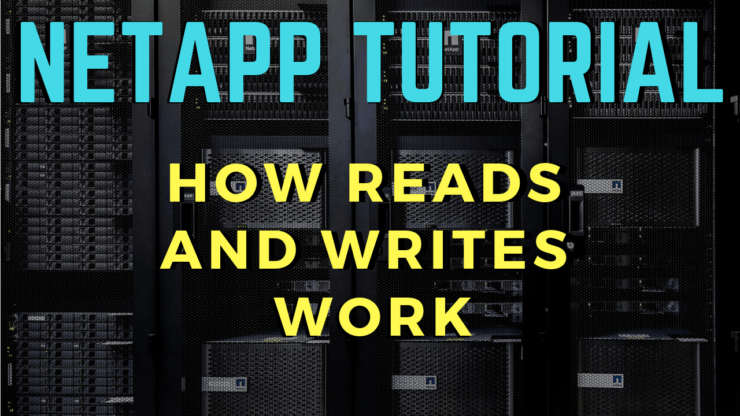
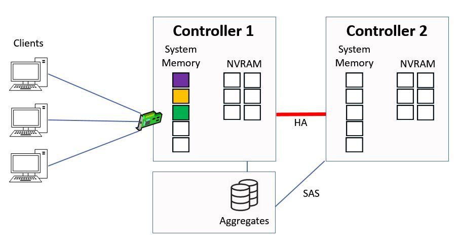
In this example we’re going to look at how reads and writes work to an aggregate which is owned by Controller 1.
How WAFL Works Example
Direct Data Access - Writes
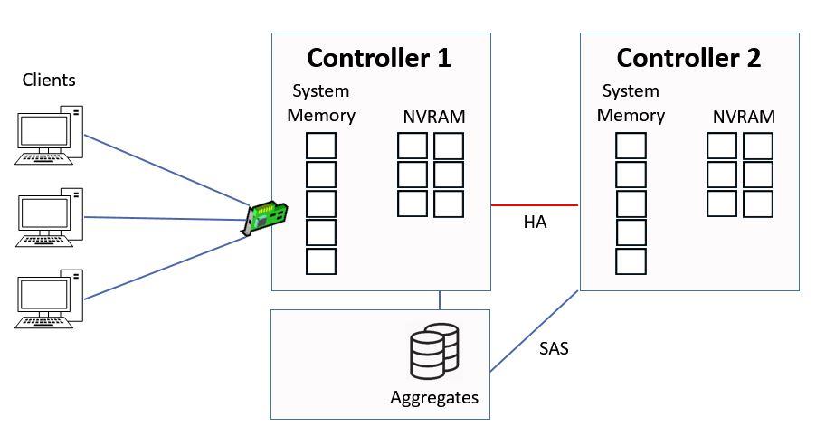
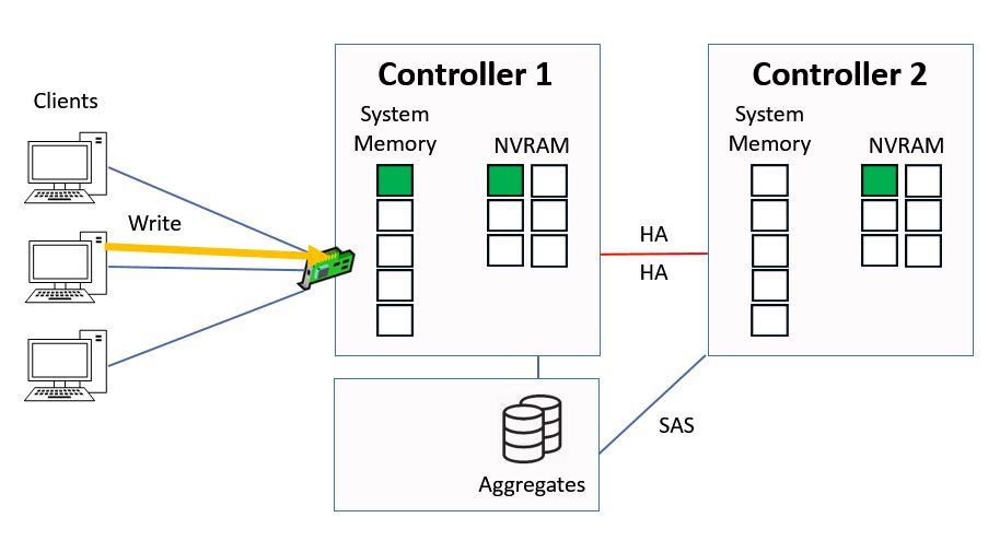
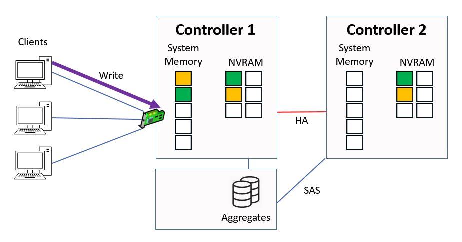
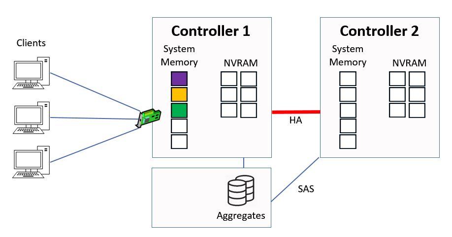
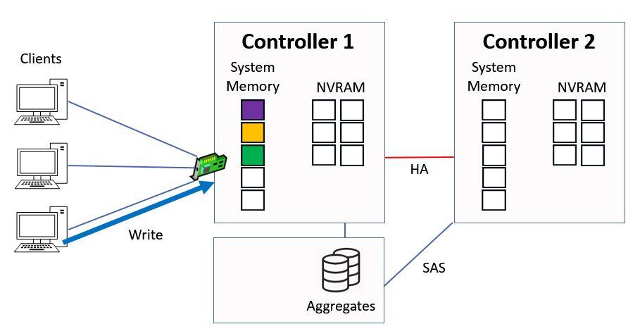
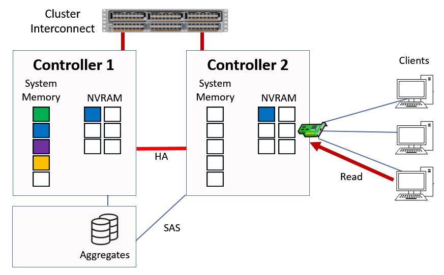
We're going to look at direct data access first. This is where clients hit a logical interface which is homed on the same controller that owns the aggregate. A client sends in a write request for ‘green’ data.
Direct Data Access - Write
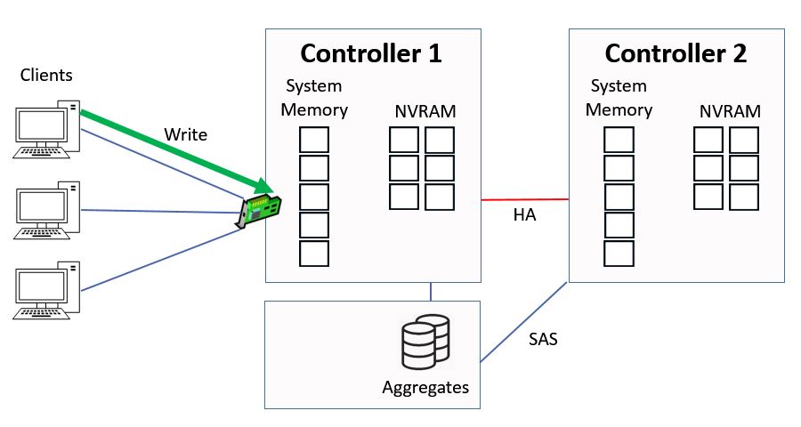
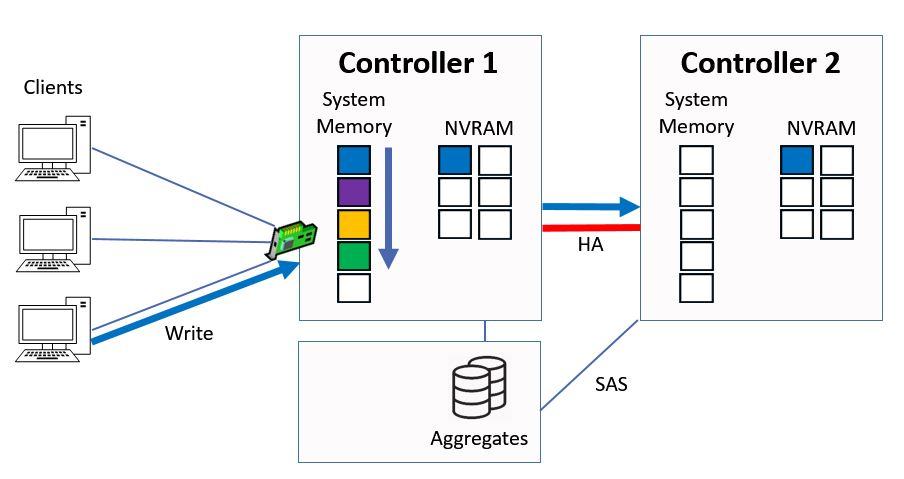
It gets written to system memory on Controller 1, and to NVRAM on both Controller 1 and its high availability peer of Controller 2. The NVRAM mirroring happens over the HA connection between the two Controllers.
Data Written to System Memory and NVRAM
The data is written into NVRAM on both controllers, but into system memory on Controller 1 only. The system memory cache is a limited resource and we want to maximise its use.
I’ll explain the use of system memory and NVRAM after you’ve seen how the read process works.
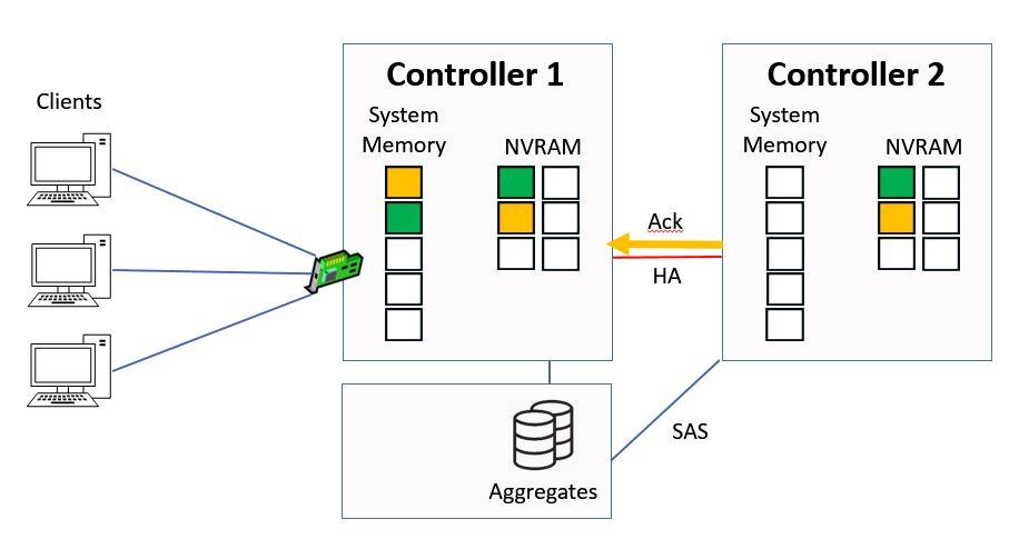
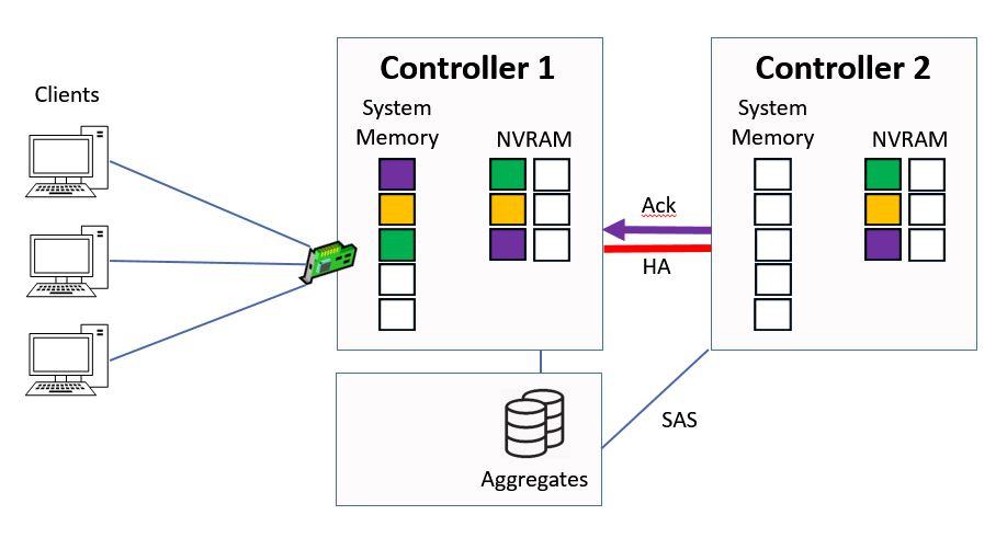
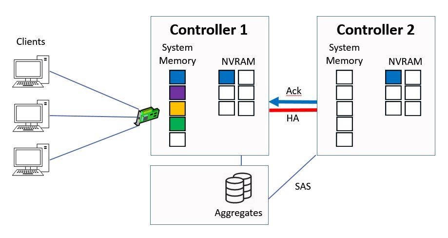
When Controller 2 has written the data into NVRAM it will send an acknowledgement back to Controller 1, again over the HA connection.
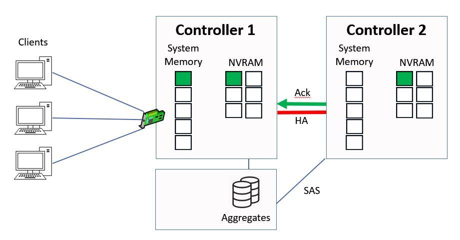
Ctrl 2 sends Ack to Ctrl 1
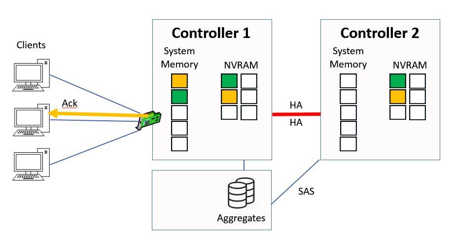
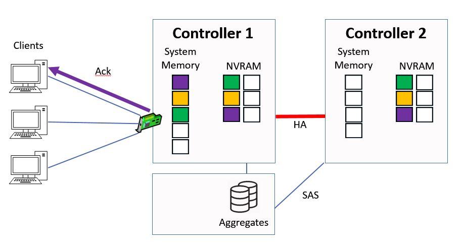
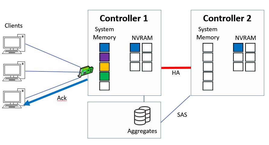
Controller 1 will then send an acknowledgement back to the client.
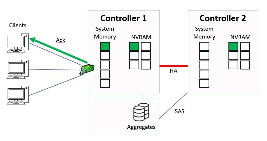
Ctrl 1 sends Ack to Client
Next another client sends in a write request, this time for ‘yellow’ data.
Another Write Request
Again it gets written into system memory on Controller 1, and into NVRAM on Controller 1 and 2.
The yellow data gets put into the top slot in our system memory cache on Controller 1, and the other data gets bumped down a slot.
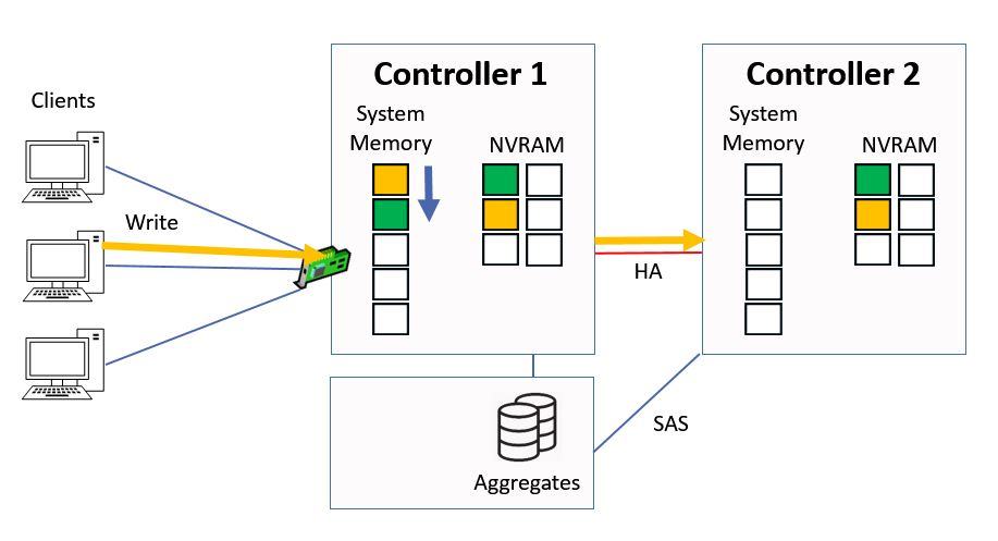
Written to System Memory and NVRAM
Controller 2 will send an acknowledgement to back to Controller 1 once it's got the data in NVRAM.
Ctrl 2 sends Ack to Ctrl 1
Then Controller 1 will then send the acknowledgement back to the client.
Ctrl 1 sends Ack to Client
Next we have a third write request that comes in from a client, for ‘purple’ data this time.
Another Write Request
The same process happens again, where it gets written into system memory on Controller 1 and to NVRAM on both Controllers. Again the purple data goes into the top slot in the system memory, and all the other data in the memory cache gets bumped down a slot.
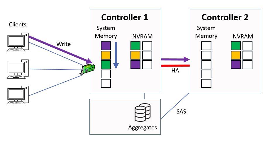
Written to System Memory and NVRAM
Controller 2 sends the acknowledgement back to Controller 1 once it's been written to NVRAM.
Ctrl 2 sends Ack to Ctrl 1
Then Controller 1 sends the acknowledgement back to the client.
Ctrl 1 sends Ack to Client
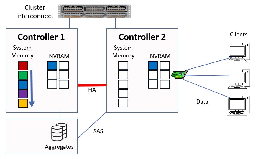
At this point NVRAM is half full and it's time to write the data to disk.
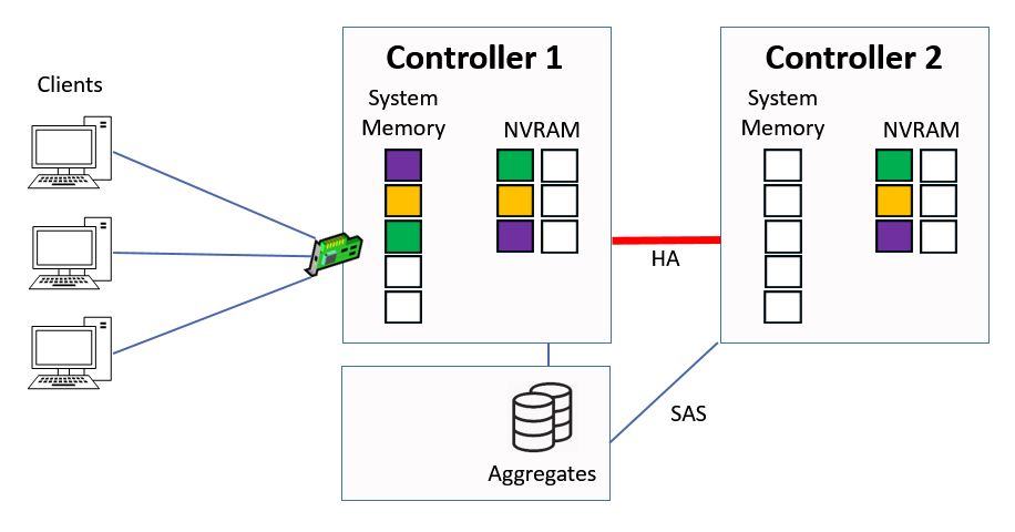
NVRAM is Half Full
We do this in a consistency point.
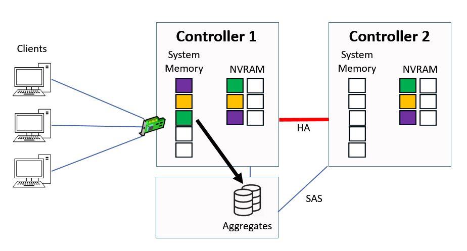
Consistency Point (CP)
Once the data has been written to disk we flush the NVRAM and it's time to start the process again.
Flush NVRAM
We'll come back to this point later in this post, but first let's talk about consistency points (CPs), NVRAM, and what happens when there's an HA takeover.
Data is written to disk in a Consistency Point when any of these events occur:
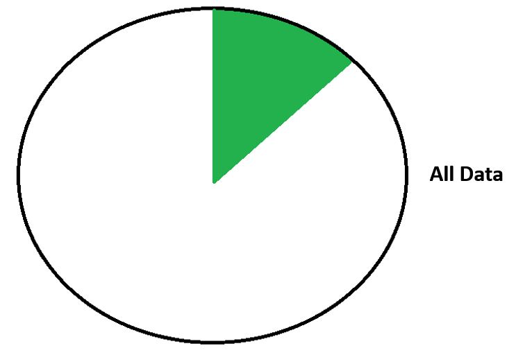
- NVRAM is half full. The system needs to leave some room for new writes coming in while it writes the data to disk, so the Consistency Point is taken when NVRAM is half (not completely) full.
- 10 seconds have passed since the last CP. We don't want to wait too long between taking consistency points, so a new CP will be taken if 10 seconds have elapsed since the last one.
- When a snapshot is taken. A snapshot is a consistent point in time image of the file system.
- When an administrator shuts down the system. The system needs to be in a consistent state when it is shut down so all pending writes will be written to disk.
Why do we have NVRAM?
Acknowledgements are sent to clients as soon as the data is written into memory. This occurs before the data is written to disk and optimizes performance, because it's much quicker to write to memory than it is to write to disk. As far as the client is concerned, the data is written to permanent storage, even though it hasn't actually been written to disk yet.
System memory is DRAM dynamic memory, it does not survive a power failure. If there was a power outage at this point when the data was still in memory but before it had been written to disk, we could have a problem because the contents of system memory are lost. If data was only written to system memory this would cause an inconsistent state because as far as the client is concerned the data has been written to permanent storage, but we would now have lost it on the Controller.
Our solution for this is NVRAM. NVRAM stands for Non Volatile RAM, meaning it survives a power outage. If we lose power before the data is written to disk, it can be recovered from NVRAM so we don't lose it.
NVRAM will write the data back into system memory, and from there it will be written to disk in the next consistency point.
The data is written to NVRAM on both Controllers in an HA pair so that if there is a takeover the HA peer has the data and can write it to disk.
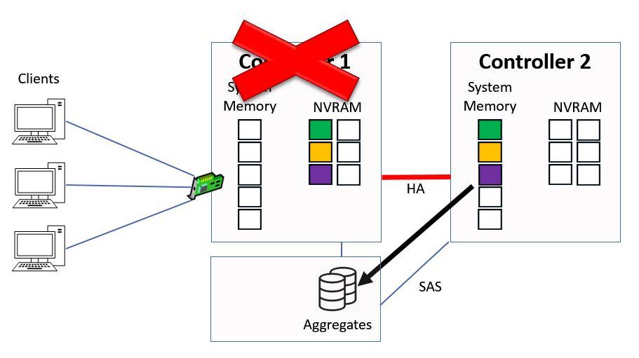
Looking at our example again, let's say that Controller 1 fails due to a power outage. It will still have the pending writes in its NVRAM, and we also have the pending writes in NVRAM on Controller 2 because they were sent to both Controllers.
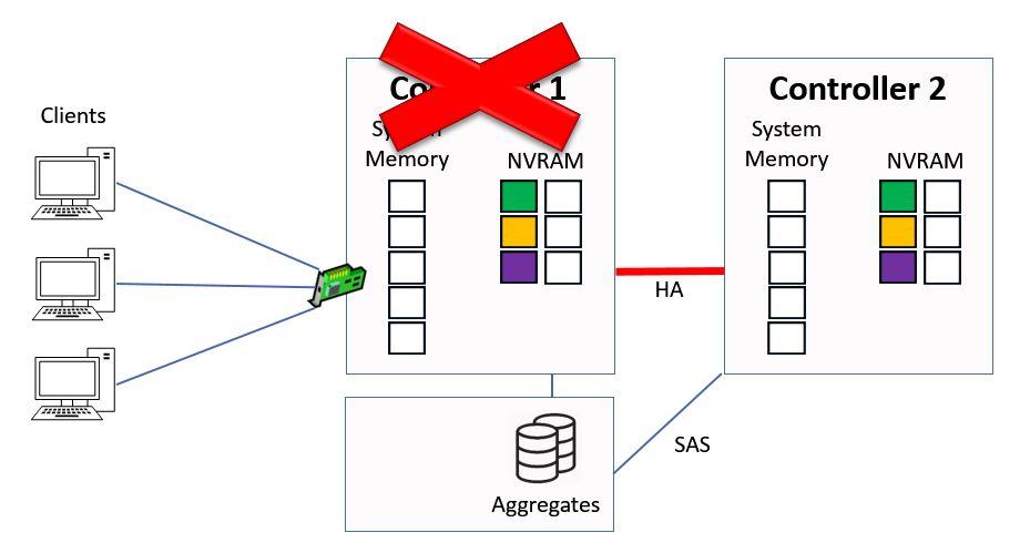
Controller 1 Failure
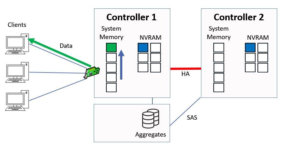
At this point Controller 2 will take over ownership of Controller 1's aggregates through high availability, it will then copy the pending writes into system memory from NVRAM.
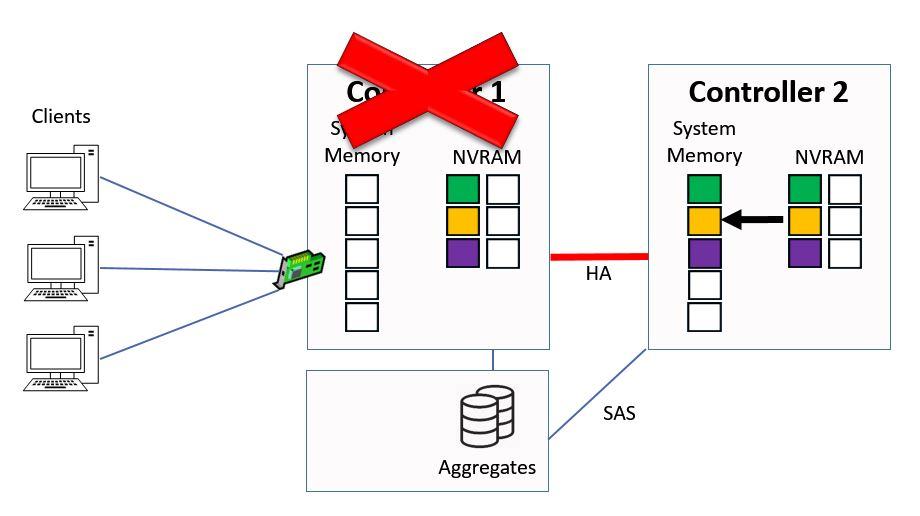
Controller 2 copies NVRAM to System Memory
They will then be written down to the aggregates in the next consistency point.
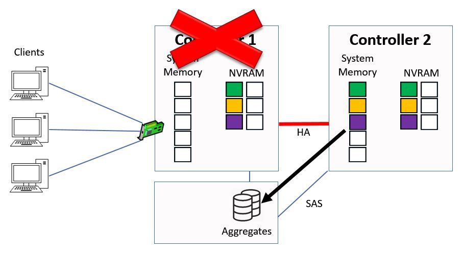
Consistency Point from Controller 2
At that point we will flush the NVRAM on Controller 2 and we start the process again.
Flush NVRAM on Controller 2
WAFL – The Write Anywhere File Layout
This is a good time to talk about WAFL, the Write Anywhere File Layout. WAFL is optimized for writes.
As you saw in the previous example it writes many operations to disk at once in a single sequential consistency point. This improves write performance because it doesn't do separate writes to disk and then send an acknowledgement for each individual client request.
The reason WAFL is called the Write Anywhere File Layout is because all data can be written anywhere on disk. It doesn't have to write metadata to fixed locations like many other file systems do (metadata is data about other data, for example date created and file size). This reduces the number of disk seek operations and improves performance.
Let's see how that works. Here we're looking at a disk that's being used by another file system which has got fixed locations on the disk for metadata.
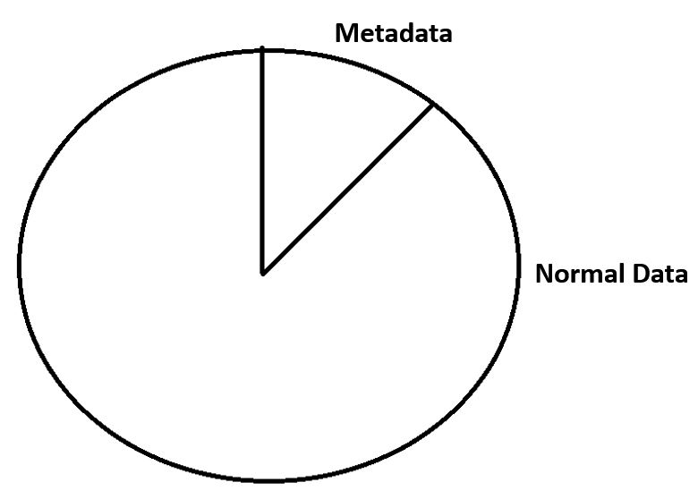
Other File Systems
We've got some existing data on there, so you can see we've got our metadata in the metadata section, and our normal data on the other section.
Other File Systems - Existing Data
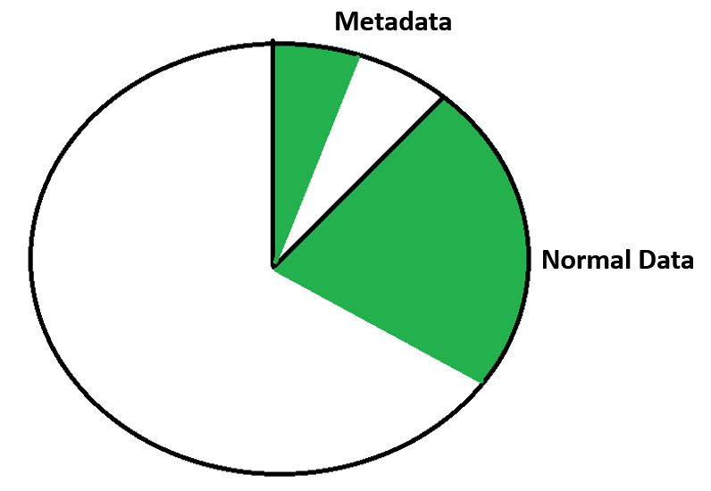
If we then write some new data to that disk, we need to seek to the metadata section for the metadata and then the normal section for our normal data. The disk head is going to be moving between those sections. Whenever we're doing disk seeks it takes time and decreases the performance.
Other File Systems - New Data
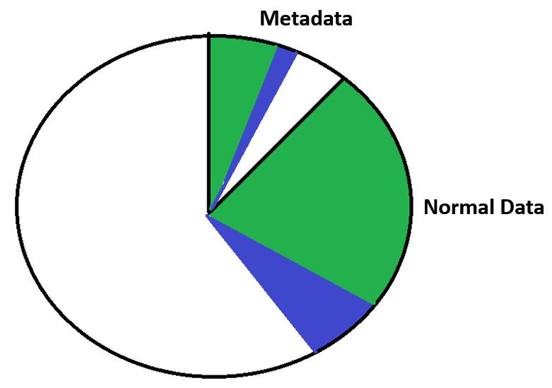
With WAFL we don't have fixed locations on disk, all data can be written anywhere.
WAFL Write Anywhere File Layout
Here we're looking at our existing data with WAFL.
WAFL - Existing Data
We can write new data sequentially so we don't have to seek between different sections, which improves our write performance.
WAFL - New Data
Direct Data Access – Writes (Continued)
Okay, this is where we last left off when we were looking at how our writes worked on our Controllers. We had just completed a consistency point in Controller 1 and flushed NVRAM on both Controllers.
Direct Data Access - Writes (Continued)
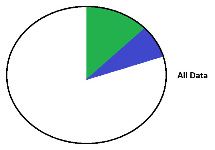
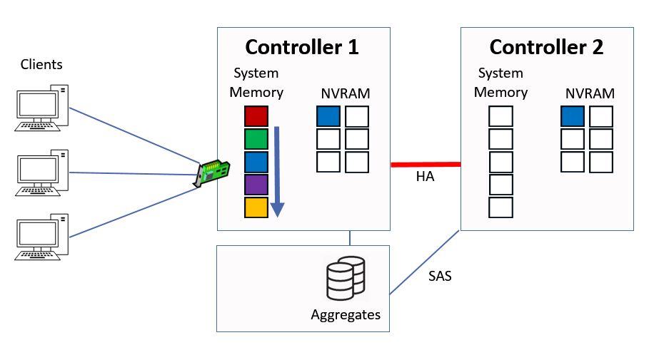
Next let's say we have another write request, this time for ‘blue’ data.
Another Write Request
We do the same again, we write it into system memory on Controller 1 and into NVRAM on both Controllers, and again the contents of system memory on Controller 1 get bumped down a slot.
Written to System Memory and NVRAM
Controller 2 will send the acknowledgement back to Controller 1 when it's in NVRAM.
Ctrl 2 sends Ack to Ctrl 1
Controller 1 will then send the acknowledgement to the client.
Ctrl 1 sends Ack to Client
Direct Data Access - Reads
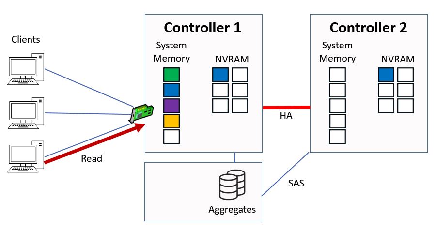
Next we have a client send in a read request for ‘green’ data.
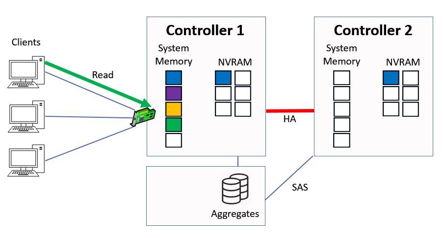
Client Sends Read Request
The Controller checks its system memory first, sees that it's there and then immediately sends that data back to the client from system memory. This is much quicker than if it had to serve it from disk.
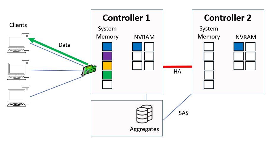
Ctrl 1 Serves Data from System Memory
Whenever we have a read or write the data gets cached, so the green data moves to the top slot in the system memory.
Data Moves to Top of System Memory
Everything else gets bumped down a slot.
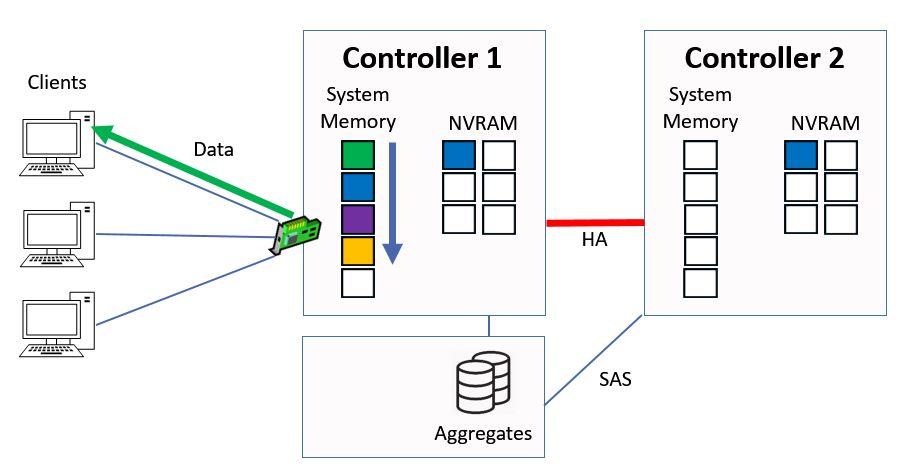
Other Data is Bumped Down
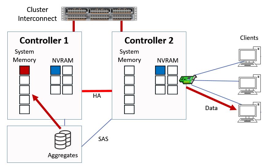
Next we have a read request for ‘red’ data.
Another Read Request
In this case it's not in the memory cache, so the Controller has to fetch it from disk, it will then be cached into the top slot in system memory and sent to the client.
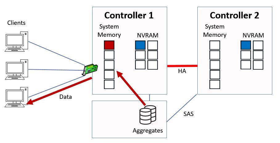
Ctrl 1 Serves Data from Disk
Again the existing contents of system memory are bumped down a slot.
Data is Cached in System Memory
Indirect Data Access – Read Requests
The previous example showed how reads and writes work for direct data access where the client hits a logical interface which is homed on the same Controller that owns the aggregate. Now let's take a look at indirect data access, where the client hits a logical interface which is on a different Controller than the Controller which owns the aggregate.
We've stepped back one step here. The client sends in a read request for that red data again, but here we're hitting a logical interface on Controller 2.
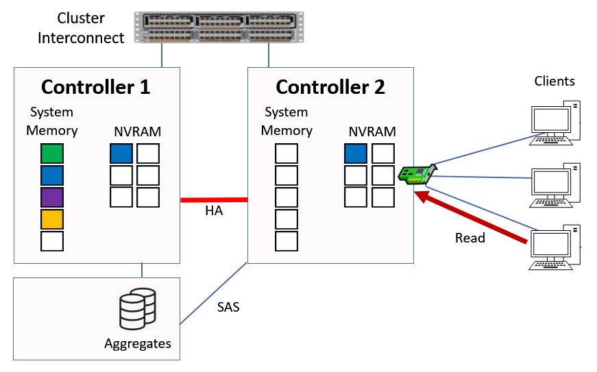
Indirect Data Access
When that happens the read request will be sent to Controller 1 by Controller 2 over the cluster interconnect. Controller 1 will first check to see if it has the data in system memory.
Read Request is sent to Controller 1
It doesn't in this example, so it will fetch the data from disk, it will then be written into the top slot in system memory and the data will be sent over the cluster interconnect out to the client via Controller 2.
Ctrl 1 Serves Data from Disk
The contents of the memory cache on Controller 1 will again be bumped down a slot.
Data is Cached in System Memory
Notice that it's the memory cache on Controller 1 which is used here rather than on Controller 2. This is good because it means that whenever a read request comes in and hits any Controller in a cluster, we're going to use the cache on the Controller which owns the aggregate. This optimizes the use of the cache on each Controller.
Indirect Data Access – Write Requests
That was how indirect read requests work. Indirect write requests work exactly the same way as shown before for direct data access, but just like our indirect read access the request will be sent over the cluster interconnect onto the Controller that owns the aggregate. Again it's the memory cache on the Controller which owns the aggregate which is going to be used.
Summary
The way reads and writes were explained here was slightly simplified to make it easy to understand. The system actually uses a more intelligent algorithm rather than all reads and writes being cached and going into the top slot in memory.
Performance optimizing algorithms are used to distinguish high value randomly read data from sequential and or low value data, and maintain that data in the cache to avoid time consuming disk reads.
Spinning hard drives give reasonably good performance for large sequential reads, it's for random reads where you'll see a big difference in the performance from when we use the cache or when we use disks. Those sequential reads can be large so we don't want to take up all the space in our cache for sequential data where we're not going to get a big performance boost.
Another technique which optimizes the performance is readahead. Readahead is a proactive mechanism that enables the system to detect and improve performance for read patterns. When a pattern of common reads is detected the whole pattern is cache into memory.
This is the first of a three part series, the next two parts expand on this post to explain how reads and writes are handled when NetApp VST caching technologies are deployed.
Join me for Part 2 here: Flash Cache – NetApp VST Virtual Storage Tier
And Part 3: Flash Pool – NetApp VST Virtual Storage Tier
Additional Resources
NetApp FAQ - Consistency Points
Wikipedia - Write Anywhere File Layout
Click Here to get my 'NetApp ONTAP 9 Storage Complete' training course.